Final report PDF: Team_A3_Lu_Tian_Wang_final_report
Final Video
Final Poster Documents
Here’s the PDF: Final Poster PDF (compressed to be able to upload to WordPress, for a full size see Google Drive link)
Here’s the PPTX: Final Poster PPTX (images are compressed to be able to upload to WordPress, for full size see Google Drive link)
Johnny Tian’s Status Report
Accomplishment
- All updated parts printed
- updated batter pack: make it slightly bigger to allow the battery smoothly sliding in and out for charging and plugging cords.
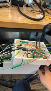
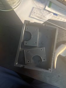
- update pi casing: make it wider and longer to fit in the cables.
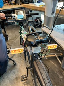
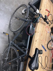
- bike assembled (picture in team status report)
- cable sorted to prevent tangle with wheels.
- Heat shrinked all connection points to prevent shorting with other parts.
- Additional nuts installed in pi casing to allow more stable top board display.
Schedule
- Finished Assembling hardware and electrical soldering
- Finished printing parts
- Finished All cads
Plan for Next Wek
- Make Poster
- Make final report
- Prepare backup parts in case accidents
- Water-proof bike after testing.
Documents

Jason Lu’s Status Report for 4/27
This Week’s Work
- Worked on final presentation slides and presented them
- Worked with team on getting everything installed onto the bicycle and hooked up
- Spent a little bit of time continuing to figure out a solution for the magnetometer
Schedule
Out of the three deliverables from the last status update, I made progress on all three two (in orange) but did not finish them. Most of my time was spent getting everything working on the bicycle.
- Get magnetometer into working state for final demo
- Make alerts on UI less noisy
- Complete more tests
Upcoming Deliverables
The main deliverables (aside from the class assignments such as video, report, etc.) for this week are essentially the same as last week, except changing “complete more tests” to “complete all tests”:
- Get magnetometer into working state for final demo
- Make alerts on UI less noisy
- Complete all tests
State of the UI
Here’s a more detailed rundown of what the main changes were to the UI since the last update:
Making the UI less “flickery” (part 2)
As a recap of what this is for: When we were testing, we noticed that the system is very “flickery” in the sense that the blind spot indicators, range indicators, and alerts can change their values very rapidly. For example, the blind spot indicators would show up and disappear pretty quickly which is not a good experience for the user.
I implemented some throttling last cycle, but this week I added an additional change to only show the blind spot indicators if the vehicle is moving towards you (velocity is negative). This seemed to reduce the amount of false blind spot indicators further.
I also disabled the forward/rear collision warnings as they are too sensitive right now. We will need to discuss whether this is a feature we want to keep.
Magnetometer
There was a lot of continued frustration this past week getting the magnetometer to work correctly. Despite doing things like comparing my code to what Adafruit is doing in their library and trying different functions in my I2C library, nothing got my code to work.
However, I noticed that with the calibration data, using Python and Adafruit’s Python library for the MMC5603 actually gives good results! I’m still mystified as to why their code works and mine doesn’t, and I suspect that I’ll need a logic analyzer to see the I2C messages to figure out why.
So instead, my new approach is to write another Python script to talk to the magnetometer using Adafruit’s library, and then use a pipe (like we’re doing with the radar data) to send it over to the JavaScript UI code.
Team Status Report for 4/27
Risk and Plans
The biggest risk right now is something does not work as intended during integration, as we have little time to correct it. We were facing issues with our turn signals, which we realized were due to the misuse of the transistors. It turned out that we were putting way too much current through them. This could have been mitigated if we read the datasheet carefully. This was a good reminder for us to rely on datasheets instead of our “confirmation bias” while integrating, and minimizing the unnecessary risks. However, as the deadline approaches, there are only little things we can do if anything goes out of plan. If this happens, we will try to mitigate the effects by identifying the key components that need to work first and prioritizing their functionality. This will let us reach our MVP.
Changes in Design
- Due to testing, we notice there are times where led will slightly light up when the gate is connected to source. From our 220 knowledge we know this shouldn’t be the case for a N mosfet. After testing, we notice there are current going from Vcc(5v) to the gate into pi. This little current is driving the leds and make them very dimmly lightup. Hence we suspect the MOSFET could be broken. Also we checked the datasheet, the max current going through each of the transistor needs to be no greater than 500mA. However, we are only putting 6 ohm resistor in series with them, which is driving almost 1A of current. Then we switched to 10 ohm resistor, which solves this problem. Even thought this can lead to the leds not running on their full capacity (1W each), through our testing, this is still able to satisfy our visibility requirements.
Schedule Updates
Here’s the Gantt chart as of writing on 4/27:
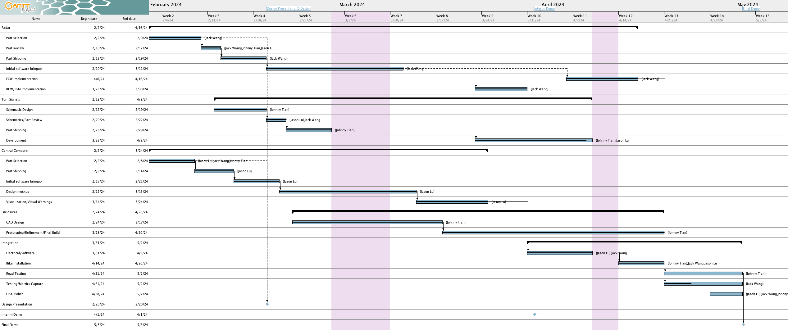
Here are the schedule updates since last week:
Completed tasks 
- Enclosures have all been printed out and installed onto the bicycle (“Prototyping/Refinement/Final Build” task and “Bike Installation” task are complete)
- There was an accident on 4/27 where we broke the left rear turn signal mount due to the bicycle falling over, so that will need to be fixed
Lagging tasks 
The following tasks are behind:
- Turn signal development – Some movement on this the past week, but still not complete – see Jason’s update for more details.
- Road Testing + Testing/Metrics Capture – We are behind on both of these tasks. We haven’t had a chance to take this out onto the road for real world testing. Furthermore, we’ve completed about 35% of the testing we need to do, whereas both tasks are due tonight. Work will have to continue this next week and will therefore run in parallel with final polish
Miscellaneous task changes
- For the “Prototyping/Refinement/Final Build” task and “Bike Installation” task, we are going to exclude sealing the system for waterproofing until as late as possible, as once that happens we will not be able to easily access the internals of the systems.
- Feedback capture task deleted since we’re no longer having ease of installation as a use case requirement anymore
Special Topics
List all unit tests and overall system test carried out for experimentation of the system. List any findings and design changes made from your analysis of test results and other data obtained from the experimentation.
- Power consumption: We have tested the power consumption of the system. The results were 1.64 A peak current draw (which gives us a good idea of the worse case current usage) and 1.14 A average current draw, with the Raspberry Pi’s current draw being mostly responsible for the difference between the peak and average current draw. During the initial tests, we realized that the current going through the transistors was too high which were destroying them (we were pushing more than double the current limit), causing us to change to larger resistors for the LEDs.
- Radar distance: We have conducted some radar tests, including max detection distance to the rear and the side. For the rear, we can detect a car up to 25.14 m on average, whereas on the side (edge of car is 6 feet away from center of bicycle, simulating being in another lane), the range drops to 11.84 m on average which is below our 14 m requirement. Interestingly, the car was actually detected out at 18 m and again around 14 m briefly, which suggests that perhaps the radar is capable of picking the car that far out but we just need to tune the system.
- Turn Signal Range: We were able to test the daytime visibility of the turn signals, reaching a result of > ~112 ft (if measuring using Google maps) or at least 104 ft (since we measured 98 inches of width per parking spot, and there were at least 13 parking spot widths of distance). Either way, this exceeds the 100 ft daytime visibility requirement. We still need to test the night time range. At this moment, no changes are needed.
- Distance Accuracy: This test needs to be redone, but preliminary results show that on average the radar has about a 3% error in its reported distance compared to what we measured using the measuring tape, which is acceptable since it’s under the 10% threshold.
- Velocity Accuracy: This test also needs to be redone, but preliminary results show that on average the radar has about a 7% error in reported velocity, although given the difficult of maintaining a precise speed in a vehicle this may not be that reliable to cite.
Jack Wang’s Status Report for 4/27/24
Personal Accomplishments:
- Final Presentation: Together with Johnny and Jason, we finished the slide deck for the Final Presentation. I made the slides about testing metrics and set up templates for other slides. During lab meeting time, I listened to other teams’ presentations, asking questions and providing feedback. I was able to hear about other people’s projects while reflecting on our project to see what to be cautious about during the final testing and integration.
- System Integration: I spent the rest of the time this week helping Johnny to finish the integration of the system onto the bike. I helped with soldering wires and making sure they were connected correctly. We had a mishap with properly using the MOSFET, where we put too much current through it. This was quickly fixed by reviewing the datasheet and changing the circuit design. The bike is fully integrated at this point.
- Testing: I did tests on the max current draw of the system, radar detection accuracy, and the visibility of the turn signals. Together with Jason, we drafted test plans and executed the tests one by one. However, more tests need to be done in the coming week, including real-world testing.
Progress:
I am currently on track to finishing the integration of the system.
Next Week:
- Integration
- Demo Preparation
Johnny Tian’ Status Report April 20th
Accomplishment
- Finish assemble half bike
- Have a 1st version of Display mount: rear radar assembly, pi&battery center assembly, display mount
- Update CAD
- PI and Battery Cad are too small, redid cad and waiting to be printed and install
- Testing
- Assembled everything but front radar for preliminary testing
Schedule
- Finished half of the bike assembling, due to parts printing time.
- Done with all cad.
Plan for Next Week
- Fully install bike for further testing
Documents
More images can be found in team status report.
Jason Lu’s Status Report for 4/20
This Two Week’s Work
- Worked on the UI code (see “State of the UI” for a description of what happened)
- Worked on final presentation slides
- Conducted some testing with my team
Schedule
Out of the two deliverables from last the last status update, I completed one (in green) and did not finish the other one (in red).
- Complete implementation of turn signal control
- Complete radar and UI integration
Upcoming Deliverables
The deliverables for this week are as follows:
- Get magnetometer into working state for final demo
- Make alerts on UI less noisy
- Complete more tests
Special Questions
As you’ve designed, implemented and debugged your project, what new tools or new knowledge did you find it necessary to learn to be able to accomplish these tasks?
Here are some tools that I had to learn for this project:
- Figma – the website that I used to mockup the UI before I implemented it.
- ElectronJS and associated tooling (e.g., Vite) – ElectronJS is the framework that I used to build the UI in. I’ve used HTML, JavaScript, and CSS, but never the ElectronJS framework itself. Additionally I had to learn how to use the associated tooling, such as how to package the application and use the build system. Some additional libraries I learned to use include:
Some other specific knowledge I got included:
- Figuring out how to use the magnetometer over I2C and how to calibrate things
What learning strategies did you use to acquire this new knowledge?
In general for tools, I learned things very informally (e.g., without watching a tutorial or reading a textbook). For Figma, I essentially just messed around with it and looked up things as needed. Figma’s official documentation was useful along with videos.
For Electron, I used their documentation and Googled things when I got stuck. Reading Github issues and StackOverflow answers was also very helpful.
For learning how to use the magnetometer, reading the MMC5603 datasheet and looking at Adafruit’s C++ library implementation was really helpful. And of course, lots of trial and error. For calibration, reading blog posts and seeing sample code proved to be very useful
For Raspberry Pi-related issues, I read posts from peoples’ blogs, the Raspberry Pi forums, questions and answers on the StackExchange network, and reading the documentation.
State of the UI
Here’s a more detailed rundown of what the changes were to the UI since the last update
Integration with radar
The implementation work was done by the previous status report, but in these two weeks Jack got the front radar working and we verified that radar and UI integration is working for both front and rear radars.
Making the UI less “flickery”
When we were testing, we noticed that the system is very “flickery” in the sense that the blind spot indicators, range indicators, and alerts can change their values very rapidly. For example, the blind spot indicators would show up and disappear pretty quickly which is not a good experience for the user.
To fix this, I implemented a deactivation delay for the blind spot indicator where each blind spot indicator must stay activated for at least 2 seconds after the last detection of a vehicle in the side lane before it is allowed to deactivate.
For the range indicator, I ended up implementing something akin to a throttling system where updates to the range indicator are throttled to 1 Hz (although in testing it before writing this I think there might be a slight bug that occasionally allows faster updates to go through).
The collision warnings are still too sensitive right now. I’ll have to think of some way to make them less sensitive.
Adventures in magnetometer calibration
In the last status report, I talked about an issue where rotating the magnetometer 90 degrees physically only reports 60 degrees. I spent a significant amount of time the last two weeks trying to calibrate the magnetometer to see if I could improve this.
In my first attempt, I used some Python calibration code that was modified from code on this Adafruit page (plotting code taken from this Jupyter notebook from Adafruit) to determine the hard iron offsets. That gave me some calibration values, except when I applied the calibration values in code the magnetometer broke even more where rotating the magnetometer by a lot only changed the heading by a few degrees.
Then, I attempted to perform a more advanced calibration using a software called MotionCal (which calculates both hard and soft iron offsets). I spent a decent amount of time getting it to build on the RPi 4 and modifying the code to take input from my Python script that interfaces with the magnetometer instead of reading from a serial port as MotionCal originally wants. This StackOverflow answer had code that I used for bridging between my Python script that interfaced with the magnetometer and MotionCal. My original idea was to create a virtual serial port that MotionCal could use directly so I didn’t have to modify MotionCal, but it turns out this solution didn’t create the type of device MotionCal wanted so I ended up having to modify MotionCal too. In the end, I effectively ended up piping data from the Python script to MotionCal.
I also used this StackExchange answer that had sample code that was helpful in determining what to send from the Python script and in what format (e.g., multiplying by 10 for the raw values) for MotionCal to work, and it was also helpful for learning how to apply the soft iron offsets once I obtained them from MotionCal.
With all these changes, I still didn’t have any improvement – rotating the magnetometer a lot would not result in a significant change in the heading :(. So, as of this writing, the magnetometer is still not functional as a compass. Oddly enough, reverting my changes seemingly no longer allows the magnetometer to work as before all this (where rotating 90 degrees is needed to report 60 degrees). I’ll need to spend some time before the demo getting this fixed, but I may just use my workaround mentioned in the last status report instead of trying to get calibration to work.
Personally, I’m starting to think that something’s wrong with our magnetometer. The plots I get when calibrating are very different from what Adafruit gets (see animation in top left corner), where my code draws three circles very far apart instead of overlapping like they get.
It turns out I actually have an IMU (MPU6050) from a previous class that I took so I could’ve used that instead of the magnetometer, but I think at this point it may be too late to switch. I’ll have to look into how much effort it’ll take to get the IMU up and running instead, but from what I remember from trying to use the IMU to calculate heading in my previous class, I will also need to do calibration for it too which might be difficult.
Jack Wang’s Status Report for 4/20/24
Personal Accomplishments:
- Radar: In the past two weeks, I finished the work of the both rear and the front radar. Two radars were able to work independently, providing data like distances and velocity. In addition, I worked on the integration of the radar with the UI that Jason developed. I introduced that we will be using Named Pipe from the last status report, and I was able to configure the set up so that the information I sent from the radar matched with the desired format that Jason was looking for in his UI. In addition, I also implemented some basic strategies to de-noise the radar detection. I did so by looking at 3 consecutive detection frames and filtering out data points that only appeared in 1 frame, which is defined as noise. I would only forward the data to the UI if the target is appearing in all 3 frames. At this point, the full radar-UI pipeline is working as desired.
- Integration: Together with Johnny and Jason, I integrated the system onto the bike. This included making sure the wiring was correct, and each module was functioning as it should be.
- Testing: We did some tests for our system based on the design requirements. I drove the car behind our bicycle setup, and we recorded data like detection distance and velocity. These results will be shared in the final presentation.
Progress:
I am currently on track to finishing the integration of the system.
Special Topic:
As you’ve designed, implemented and debugged your project, what new tools or new knowledge did you find it necessary to learn to be able to accomplish these tasks? What learning strategies did you use to acquire this new knowledge?
One of the new tools that I learned is how to properly send data between the radar and the UI. I learned how to use Named Pipe and how to pack my raw data from the radar into JSON format. I learned this by first researching strategies that could achieve our desired outcome, from which I picked the simplest solution given that we are not processing tonnes of data. After identifying the tool, I read through the implementation documentation on how to implement such a pipe. Then, I did some simple experiments and basic testing before fully utilizing it on our system.
Next Week:
- Integration
- Demo Preparation