This Two Week’s Work
- Worked on the UI code (see “State of the UI” for a description of what happened)
- Worked on final presentation slides
- Conducted some testing with my team
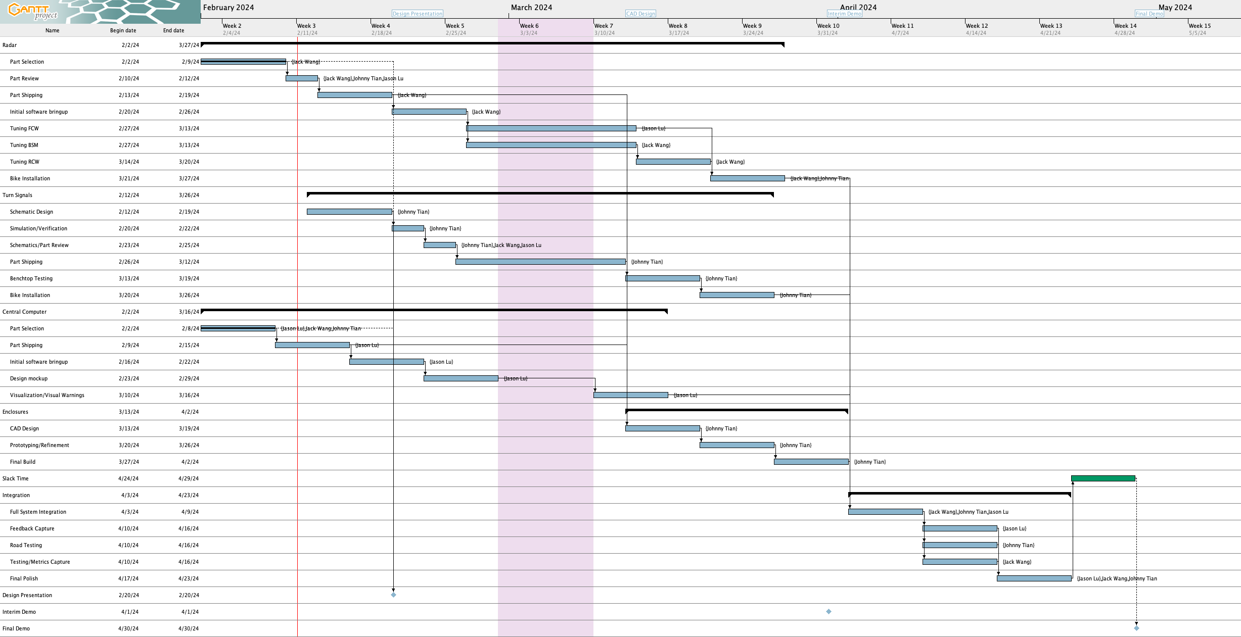
Schedule
Out of the two deliverables from last the last status update, I completed one (in green) and did not finish the other one (in red).
- Complete implementation of turn signal control
- Complete radar and UI integration
Upcoming Deliverables
The deliverables for this week are as follows:
- Get magnetometer into working state for final demo
- Make alerts on UI less noisy
- Complete more tests
Special Questions
As you’ve designed, implemented and debugged your project, what new tools or new knowledge did you find it necessary to learn to be able to accomplish these tasks?
Here are some tools that I had to learn for this project:
- Figma – the website that I used to mockup the UI before I implemented it.
- ElectronJS and associated tooling (e.g., Vite) – ElectronJS is the framework that I used to build the UI in. I’ve used HTML, JavaScript, and CSS, but never the ElectronJS framework itself. Additionally I had to learn how to use the associated tooling, such as how to package the application and use the build system. Some additional libraries I learned to use include:
- onoff – GPIO control in JavaScript
- i2c-bus – I2C control in JavaScript
Some other specific knowledge I got included:
- Figuring out how to use the magnetometer over I2C and how to calibrate things
What learning strategies did you use to acquire this new knowledge?
In general for tools, I learned things very informally (e.g., without watching a tutorial or reading a textbook). For Figma, I essentially just messed around with it and looked up things as needed. Figma’s official documentation was useful along with videos.
For Electron, I used their documentation and Googled things when I got stuck. Reading Github issues and StackOverflow answers was also very helpful.
For learning how to use the magnetometer, reading the MMC5603 datasheet and looking at Adafruit’s C++ library implementation was really helpful. And of course, lots of trial and error. For calibration, reading blog posts and seeing sample code proved to be very useful
For Raspberry Pi-related issues, I read posts from peoples’ blogs, the Raspberry Pi forums, questions and answers on the StackExchange network, and reading the documentation.
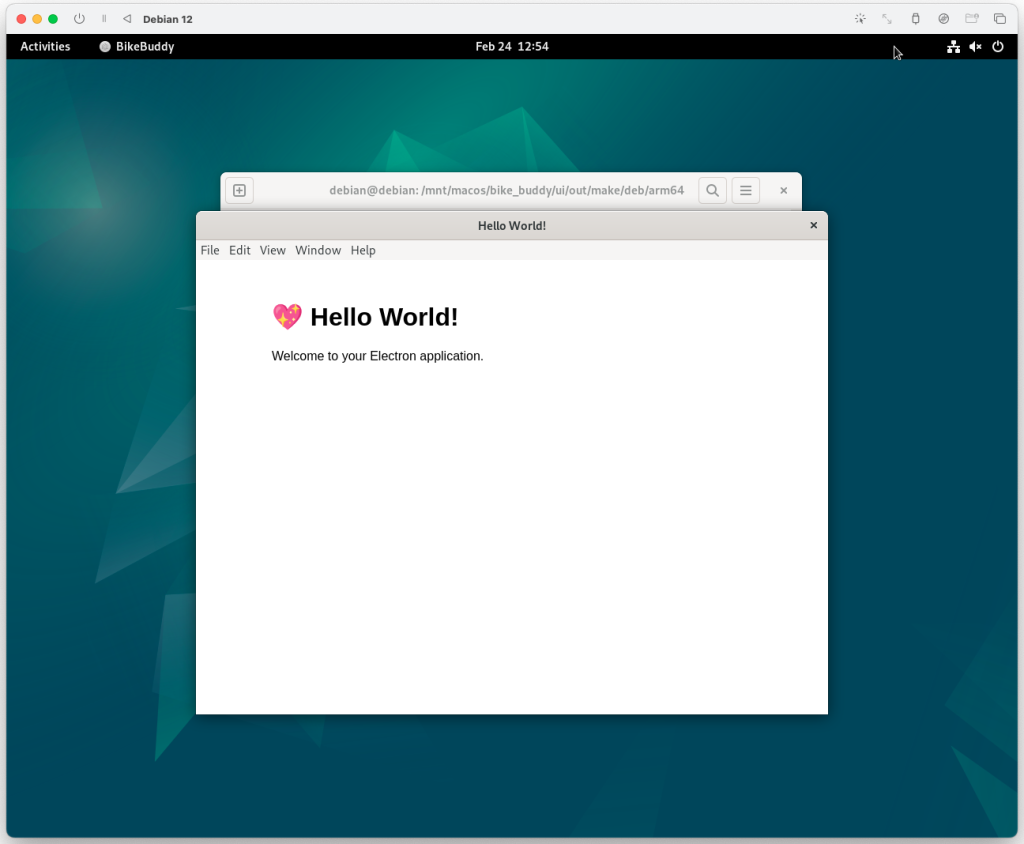
State of the UI
Here’s a more detailed rundown of what the changes were to the UI since the last update
Integration with radar
The implementation work was done by the previous status report, but in these two weeks Jack got the front radar working and we verified that radar and UI integration is working for both front and rear radars.
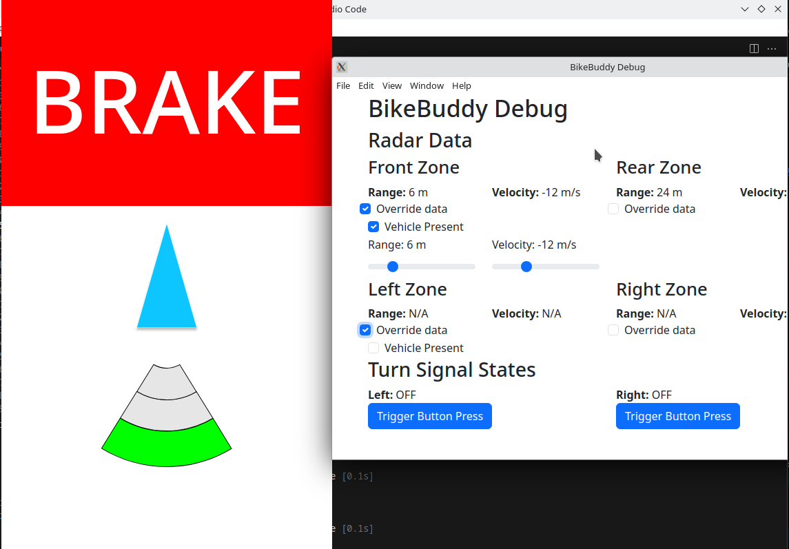
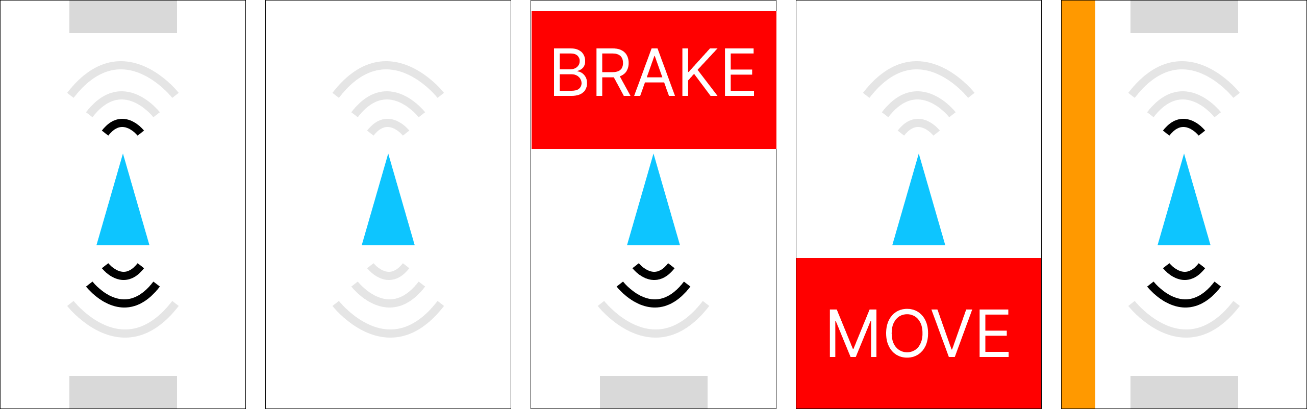
Making the UI less “flickery”
When we were testing, we noticed that the system is very “flickery” in the sense that the blind spot indicators, range indicators, and alerts can change their values very rapidly. For example, the blind spot indicators would show up and disappear pretty quickly which is not a good experience for the user.
To fix this, I implemented a deactivation delay for the blind spot indicator where each blind spot indicator must stay activated for at least 2 seconds after the last detection of a vehicle in the side lane before it is allowed to deactivate.
For the range indicator, I ended up implementing something akin to a throttling system where updates to the range indicator are throttled to 1 Hz (although in testing it before writing this I think there might be a slight bug that occasionally allows faster updates to go through).
The collision warnings are still too sensitive right now. I’ll have to think of some way to make them less sensitive.
Adventures in magnetometer calibration
In the last status report, I talked about an issue where rotating the magnetometer 90 degrees physically only reports 60 degrees. I spent a significant amount of time the last two weeks trying to calibrate the magnetometer to see if I could improve this.
In my first attempt, I used some Python calibration code that was modified from code on this Adafruit page (plotting code taken from this Jupyter notebook from Adafruit) to determine the hard iron offsets. That gave me some calibration values, except when I applied the calibration values in code the magnetometer broke even more where rotating the magnetometer by a lot only changed the heading by a few degrees.
Then, I attempted to perform a more advanced calibration using a software called MotionCal (which calculates both hard and soft iron offsets). I spent a decent amount of time getting it to build on the RPi 4 and modifying the code to take input from my Python script that interfaces with the magnetometer instead of reading from a serial port as MotionCal originally wants. This StackOverflow answer had code that I used for bridging between my Python script that interfaced with the magnetometer and MotionCal. My original idea was to create a virtual serial port that MotionCal could use directly so I didn’t have to modify MotionCal, but it turns out this solution didn’t create the type of device MotionCal wanted so I ended up having to modify MotionCal too. In the end, I effectively ended up piping data from the Python script to MotionCal.
I also used this StackExchange answer that had sample code that was helpful in determining what to send from the Python script and in what format (e.g., multiplying by 10 for the raw values) for MotionCal to work, and it was also helpful for learning how to apply the soft iron offsets once I obtained them from MotionCal.
With all these changes, I still didn’t have any improvement – rotating the magnetometer a lot would not result in a significant change in the heading :(. So, as of this writing, the magnetometer is still not functional as a compass. Oddly enough, reverting my changes seemingly no longer allows the magnetometer to work as before all this (where rotating 90 degrees is needed to report 60 degrees). I’ll need to spend some time before the demo getting this fixed, but I may just use my workaround mentioned in the last status report instead of trying to get calibration to work.
Personally, I’m starting to think that something’s wrong with our magnetometer. The plots I get when calibrating are very different from what Adafruit gets (see animation in top left corner), where my code draws three circles very far apart instead of overlapping like they get.
It turns out I actually have an IMU (MPU6050) from a previous class that I took so I could’ve used that instead of the magnetometer, but I think at this point it may be too late to switch. I’ll have to look into how much effort it’ll take to get the IMU up and running instead, but from what I remember from trying to use the IMU to calculate heading in my previous class, I will also need to do calibration for it too which might be difficult.