Here’s the PDF: Final Poster PDF (compressed to be able to upload to WordPress, for a full size see Google Drive link)
Here’s the PPTX: Final Poster PPTX (images are compressed to be able to upload to WordPress, for full size see Google Drive link)
Carnegie Mellon ECE Capstone, Spring 2024 – Johnny Tian, Jack Wang, Jason Lu
Here’s the PDF: Final Poster PDF (compressed to be able to upload to WordPress, for a full size see Google Drive link)
Here’s the PPTX: Final Poster PPTX (images are compressed to be able to upload to WordPress, for full size see Google Drive link)
Accomplishment
Schedule
Plan for Next Wek
Documents

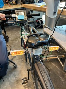
Out of the three deliverables from the last status update, I made progress on all three two (in orange) but did not finish them. Most of my time was spent getting everything working on the bicycle.
The main deliverables (aside from the class assignments such as video, report, etc.) for this week are essentially the same as last week, except changing “complete more tests” to “complete all tests”:
Here’s a more detailed rundown of what the main changes were to the UI since the last update:
As a recap of what this is for: When we were testing, we noticed that the system is very “flickery” in the sense that the blind spot indicators, range indicators, and alerts can change their values very rapidly. For example, the blind spot indicators would show up and disappear pretty quickly which is not a good experience for the user.
I implemented some throttling last cycle, but this week I added an additional change to only show the blind spot indicators if the vehicle is moving towards you (velocity is negative). This seemed to reduce the amount of false blind spot indicators further.
I also disabled the forward/rear collision warnings as they are too sensitive right now. We will need to discuss whether this is a feature we want to keep.
There was a lot of continued frustration this past week getting the magnetometer to work correctly. Despite doing things like comparing my code to what Adafruit is doing in their library and trying different functions in my I2C library, nothing got my code to work.
However, I noticed that with the calibration data, using Python and Adafruit’s Python library for the MMC5603 actually gives good results! I’m still mystified as to why their code works and mine doesn’t, and I suspect that I’ll need a logic analyzer to see the I2C messages to figure out why.
So instead, my new approach is to write another Python script to talk to the magnetometer using Adafruit’s library, and then use a pipe (like we’re doing with the radar data) to send it over to the JavaScript UI code.
The biggest risk right now is something does not work as intended during integration, as we have little time to correct it. We were facing issues with our turn signals, which we realized were due to the misuse of the transistors. It turned out that we were putting way too much current through them. This could have been mitigated if we read the datasheet carefully. This was a good reminder for us to rely on datasheets instead of our “confirmation bias” while integrating, and minimizing the unnecessary risks. However, as the deadline approaches, there are only little things we can do if anything goes out of plan. If this happens, we will try to mitigate the effects by identifying the key components that need to work first and prioritizing their functionality. This will let us reach our MVP.
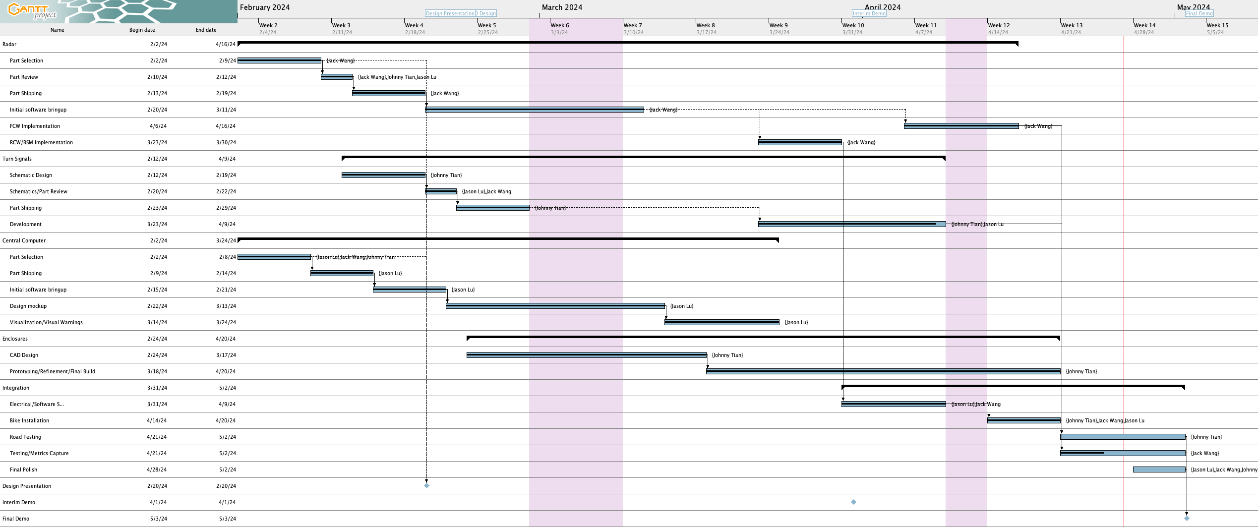
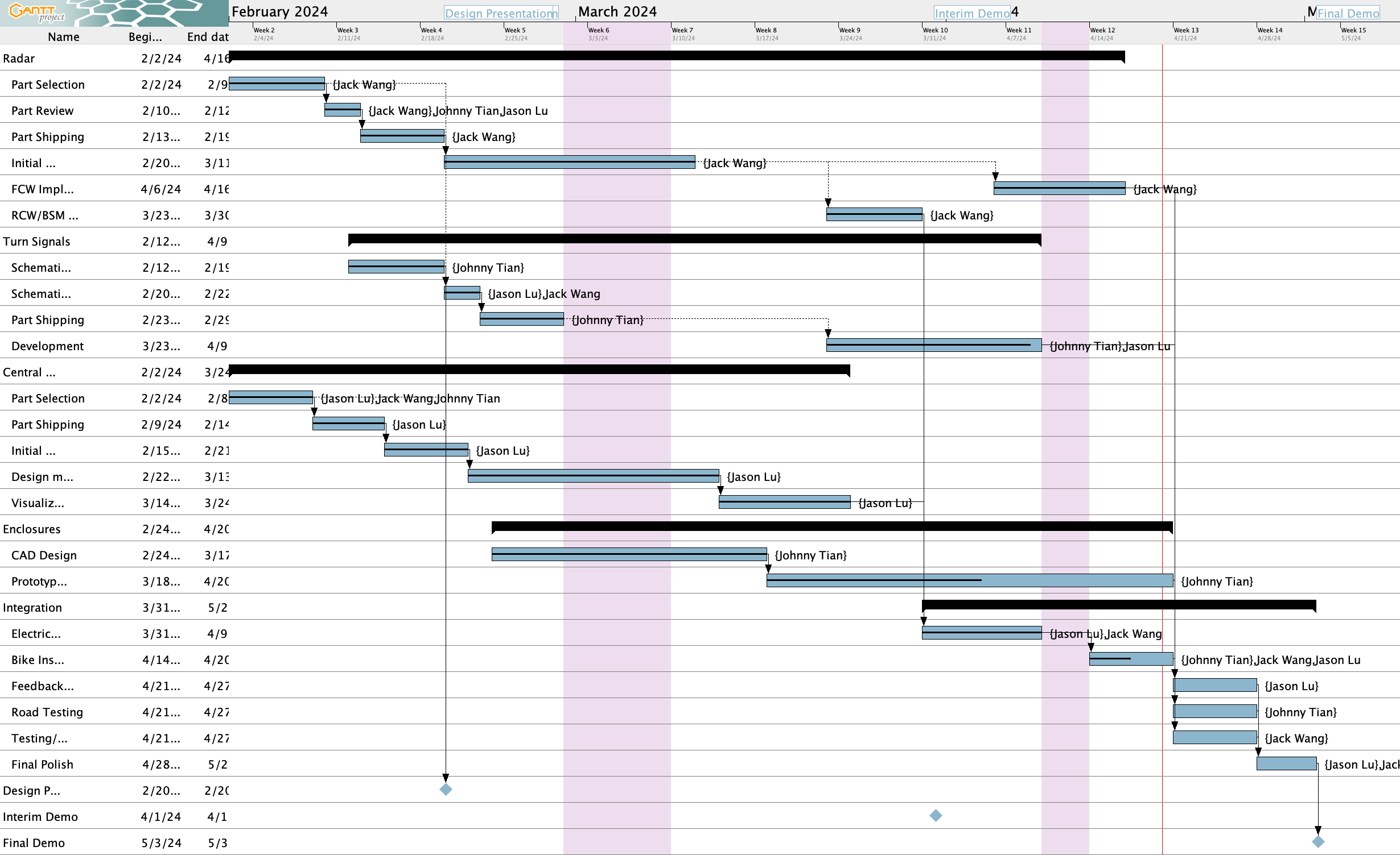
Here’s the Gantt chart as of writing on 4/27:
Here are the schedule updates since last week:


The following tasks are behind:
List all unit tests and overall system test carried out for experimentation of the system. List any findings and design changes made from your analysis of test results and other data obtained from the experimentation.
I am currently on track to finishing the integration of the system.
Next Week:
Accomplishment
Schedule
Plan for Next Week
Documents
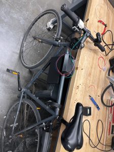
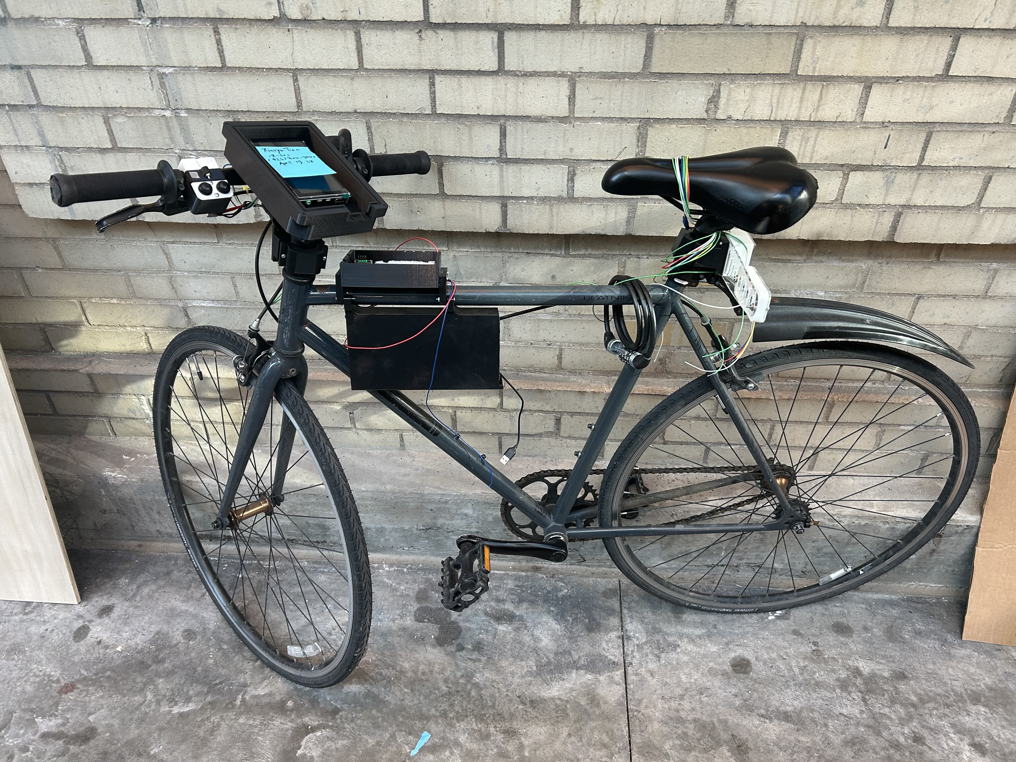
More images can be found in team status report.
Out of the two deliverables from last the last status update, I completed one (in green) and did not finish the other one (in red).
The deliverables for this week are as follows:
As you’ve designed, implemented and debugged your project, what new tools or new knowledge did you find it necessary to learn to be able to accomplish these tasks?
Here are some tools that I had to learn for this project:
Some other specific knowledge I got included:
What learning strategies did you use to acquire this new knowledge?
In general for tools, I learned things very informally (e.g., without watching a tutorial or reading a textbook). For Figma, I essentially just messed around with it and looked up things as needed. Figma’s official documentation was useful along with videos.
For Electron, I used their documentation and Googled things when I got stuck. Reading Github issues and StackOverflow answers was also very helpful.
For learning how to use the magnetometer, reading the MMC5603 datasheet and looking at Adafruit’s C++ library implementation was really helpful. And of course, lots of trial and error. For calibration, reading blog posts and seeing sample code proved to be very useful
For Raspberry Pi-related issues, I read posts from peoples’ blogs, the Raspberry Pi forums, questions and answers on the StackExchange network, and reading the documentation.
Here’s a more detailed rundown of what the changes were to the UI since the last update
The implementation work was done by the previous status report, but in these two weeks Jack got the front radar working and we verified that radar and UI integration is working for both front and rear radars.
When we were testing, we noticed that the system is very “flickery” in the sense that the blind spot indicators, range indicators, and alerts can change their values very rapidly. For example, the blind spot indicators would show up and disappear pretty quickly which is not a good experience for the user.
To fix this, I implemented a deactivation delay for the blind spot indicator where each blind spot indicator must stay activated for at least 2 seconds after the last detection of a vehicle in the side lane before it is allowed to deactivate.
For the range indicator, I ended up implementing something akin to a throttling system where updates to the range indicator are throttled to 1 Hz (although in testing it before writing this I think there might be a slight bug that occasionally allows faster updates to go through).
The collision warnings are still too sensitive right now. I’ll have to think of some way to make them less sensitive.
In the last status report, I talked about an issue where rotating the magnetometer 90 degrees physically only reports 60 degrees. I spent a significant amount of time the last two weeks trying to calibrate the magnetometer to see if I could improve this.
In my first attempt, I used some Python calibration code that was modified from code on this Adafruit page (plotting code taken from this Jupyter notebook from Adafruit) to determine the hard iron offsets. That gave me some calibration values, except when I applied the calibration values in code the magnetometer broke even more where rotating the magnetometer by a lot only changed the heading by a few degrees.
Then, I attempted to perform a more advanced calibration using a software called MotionCal (which calculates both hard and soft iron offsets). I spent a decent amount of time getting it to build on the RPi 4 and modifying the code to take input from my Python script that interfaces with the magnetometer instead of reading from a serial port as MotionCal originally wants. This StackOverflow answer had code that I used for bridging between my Python script that interfaced with the magnetometer and MotionCal. My original idea was to create a virtual serial port that MotionCal could use directly so I didn’t have to modify MotionCal, but it turns out this solution didn’t create the type of device MotionCal wanted so I ended up having to modify MotionCal too. In the end, I effectively ended up piping data from the Python script to MotionCal.
I also used this StackExchange answer that had sample code that was helpful in determining what to send from the Python script and in what format (e.g., multiplying by 10 for the raw values) for MotionCal to work, and it was also helpful for learning how to apply the soft iron offsets once I obtained them from MotionCal.
With all these changes, I still didn’t have any improvement – rotating the magnetometer a lot would not result in a significant change in the heading :(. So, as of this writing, the magnetometer is still not functional as a compass. Oddly enough, reverting my changes seemingly no longer allows the magnetometer to work as before all this (where rotating 90 degrees is needed to report 60 degrees). I’ll need to spend some time before the demo getting this fixed, but I may just use my workaround mentioned in the last status report instead of trying to get calibration to work.
Personally, I’m starting to think that something’s wrong with our magnetometer. The plots I get when calibrating are very different from what Adafruit gets (see animation in top left corner), where my code draws three circles very far apart instead of overlapping like they get.
It turns out I actually have an IMU (MPU6050) from a previous class that I took so I could’ve used that instead of the magnetometer, but I think at this point it may be too late to switch. I’ll have to look into how much effort it’ll take to get the IMU up and running instead, but from what I remember from trying to use the IMU to calculate heading in my previous class, I will also need to do calibration for it too which might be difficult.
I am currently on track to finishing the integration of the system.
As you’ve designed, implemented and debugged your project, what new tools or new knowledge did you find it necessary to learn to be able to accomplish these tasks? What learning strategies did you use to acquire this new knowledge?
One of the new tools that I learned is how to properly send data between the radar and the UI. I learned how to use Named Pipe and how to pack my raw data from the radar into JSON format. I learned this by first researching strategies that could achieve our desired outcome, from which I picked the simplest solution given that we are not processing tonnes of data. After identifying the tool, I read through the implementation documentation on how to implement such a pipe. Then, I did some simple experiments and basic testing before fully utilizing it on our system.
Although we are making good progress in integrating the system, unexpected problems are popping up, which might jeopardize our plan. At the final stage of the project, unexpected delays remain the biggest risk that we need to mitigate. Much of the mitigation of the last-minute delays has already been in place throughout the project. We made sure each component functions as desired and have plans on how to integrate them. However, we could not predict everything, as in every other engineering project. For example, we found the dimensions of the 3D-printed parts were slightly off. This meant that it would take us extra time to fix the issues, increasing the risk of running over the project deadline. We can mitigate this because we intentionally have not planned a lot of work for each member, other than integration, during the final phase of the project. So when an issue arises, the entire team can focus on addressing the issues and solving them more efficiently. We also make sure that we have a priority list of items that need to be working for our MVP, which allows us to address more important issues first when challenges come. With such planning, we hope that the chances of running over time are low as we still have some slack time for the project.
No changes to design.
Here’s the Gantt chart as of writing on 4/20:
Here are the schedule updates since last week:
The following tasks are behind:
Accomplishment
Schedule
Plan for Next week
Document
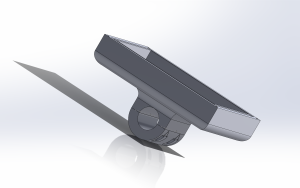
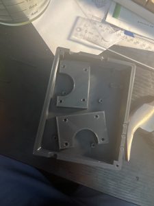
Display Mount Cad