Risk and Plans
The biggest risk right now is something does not work as intended during integration, as we have little time to correct it. We were facing issues with our turn signals, which we realized were due to the misuse of the transistors. It turned out that we were putting way too much current through them. This could have been mitigated if we read the datasheet carefully. This was a good reminder for us to rely on datasheets instead of our “confirmation bias” while integrating, and minimizing the unnecessary risks. However, as the deadline approaches, there are only little things we can do if anything goes out of plan. If this happens, we will try to mitigate the effects by identifying the key components that need to work first and prioritizing their functionality. This will let us reach our MVP.
Changes in Design
- Due to testing, we notice there are times where led will slightly light up when the gate is connected to source. From our 220 knowledge we know this shouldn’t be the case for a N mosfet. After testing, we notice there are current going from Vcc(5v) to the gate into pi. This little current is driving the leds and make them very dimmly lightup. Hence we suspect the MOSFET could be broken. Also we checked the datasheet, the max current going through each of the transistor needs to be no greater than 500mA. However, we are only putting 6 ohm resistor in series with them, which is driving almost 1A of current. Then we switched to 10 ohm resistor, which solves this problem. Even thought this can lead to the leds not running on their full capacity (1W each), through our testing, this is still able to satisfy our visibility requirements.
Schedule Updates
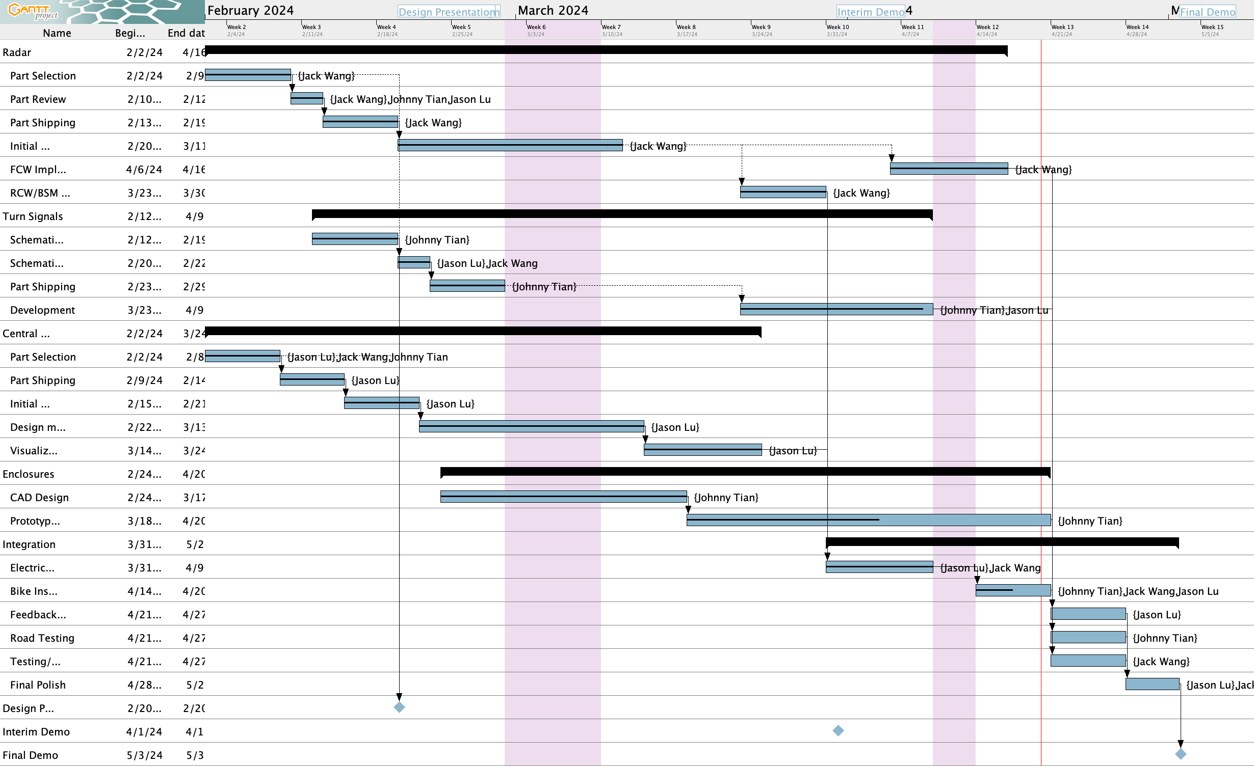
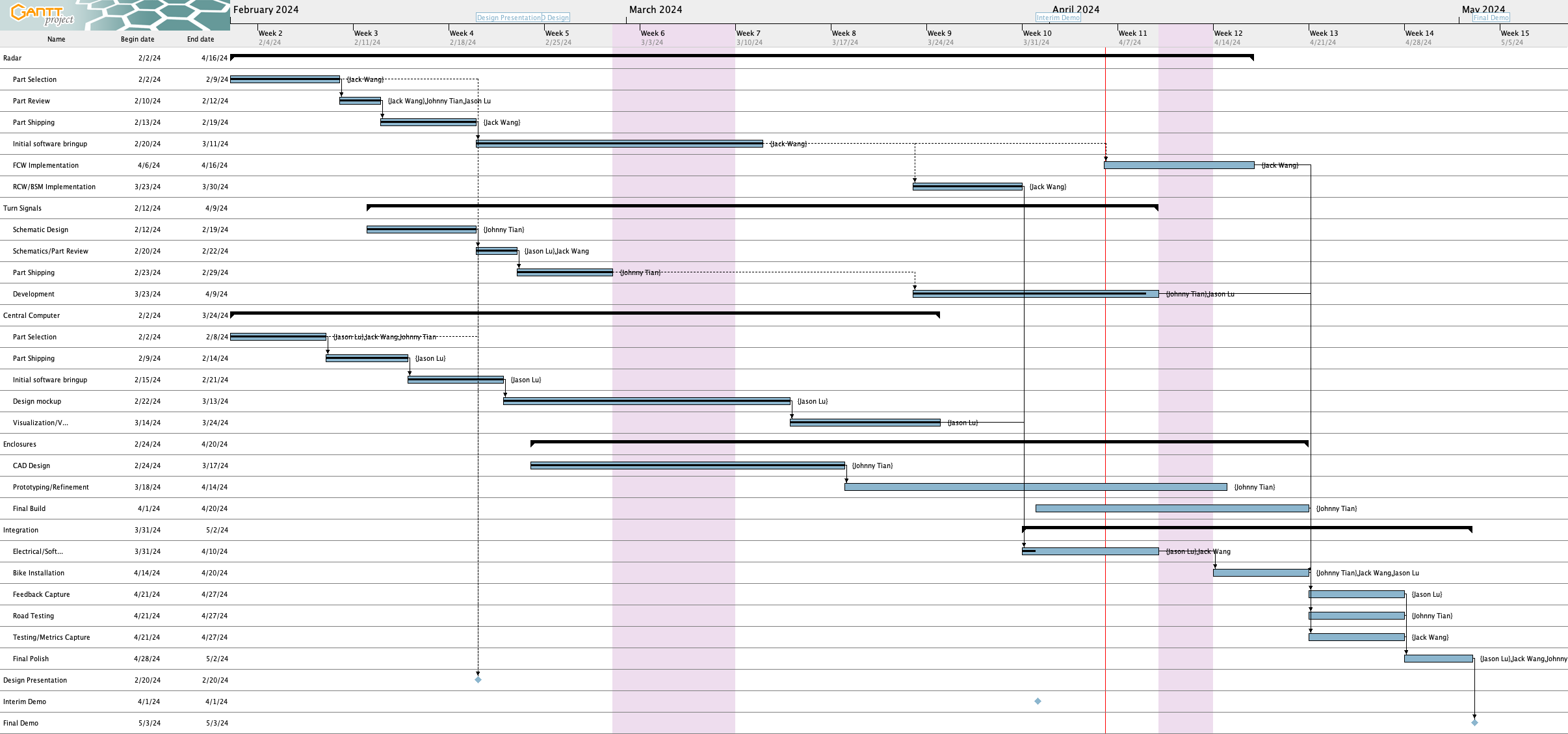
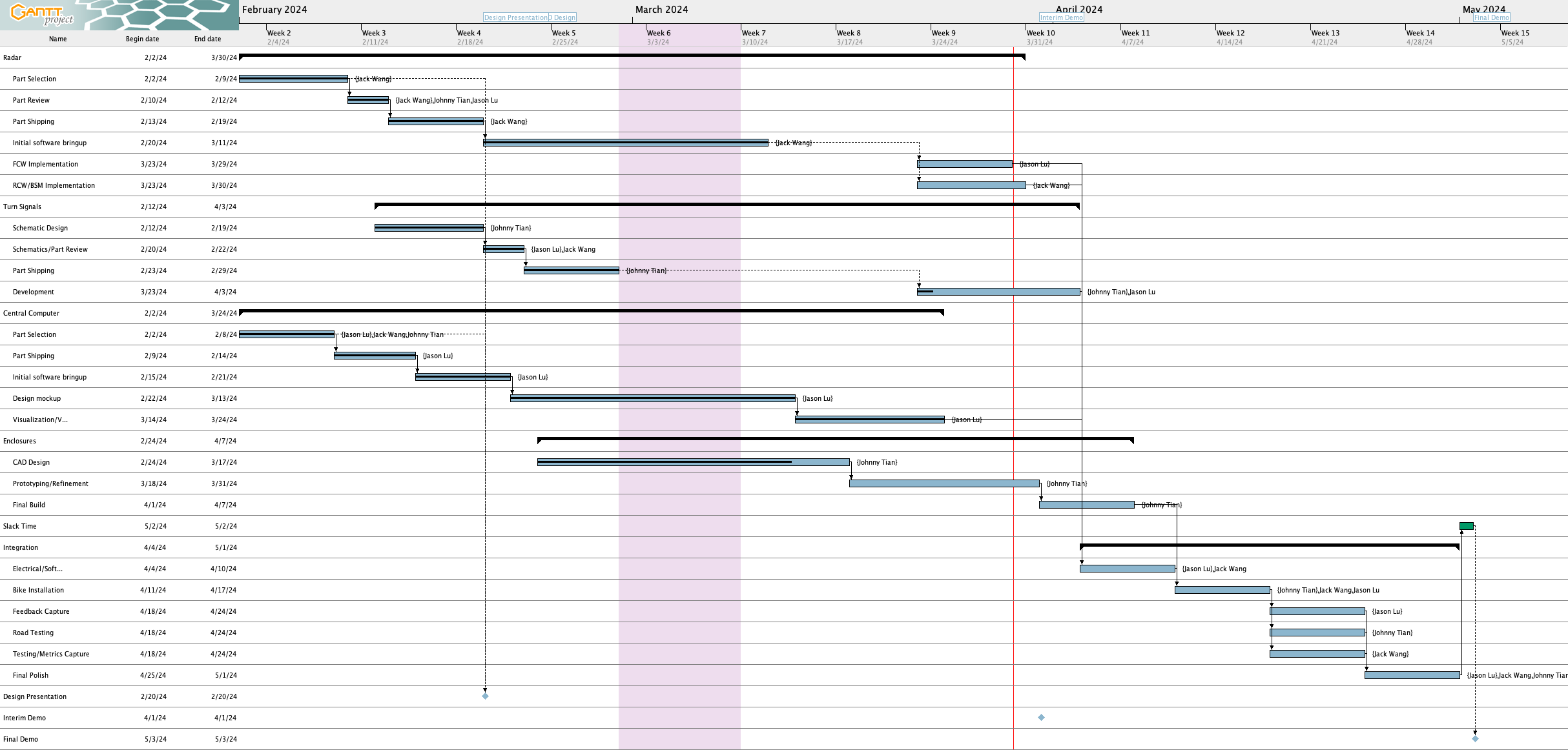
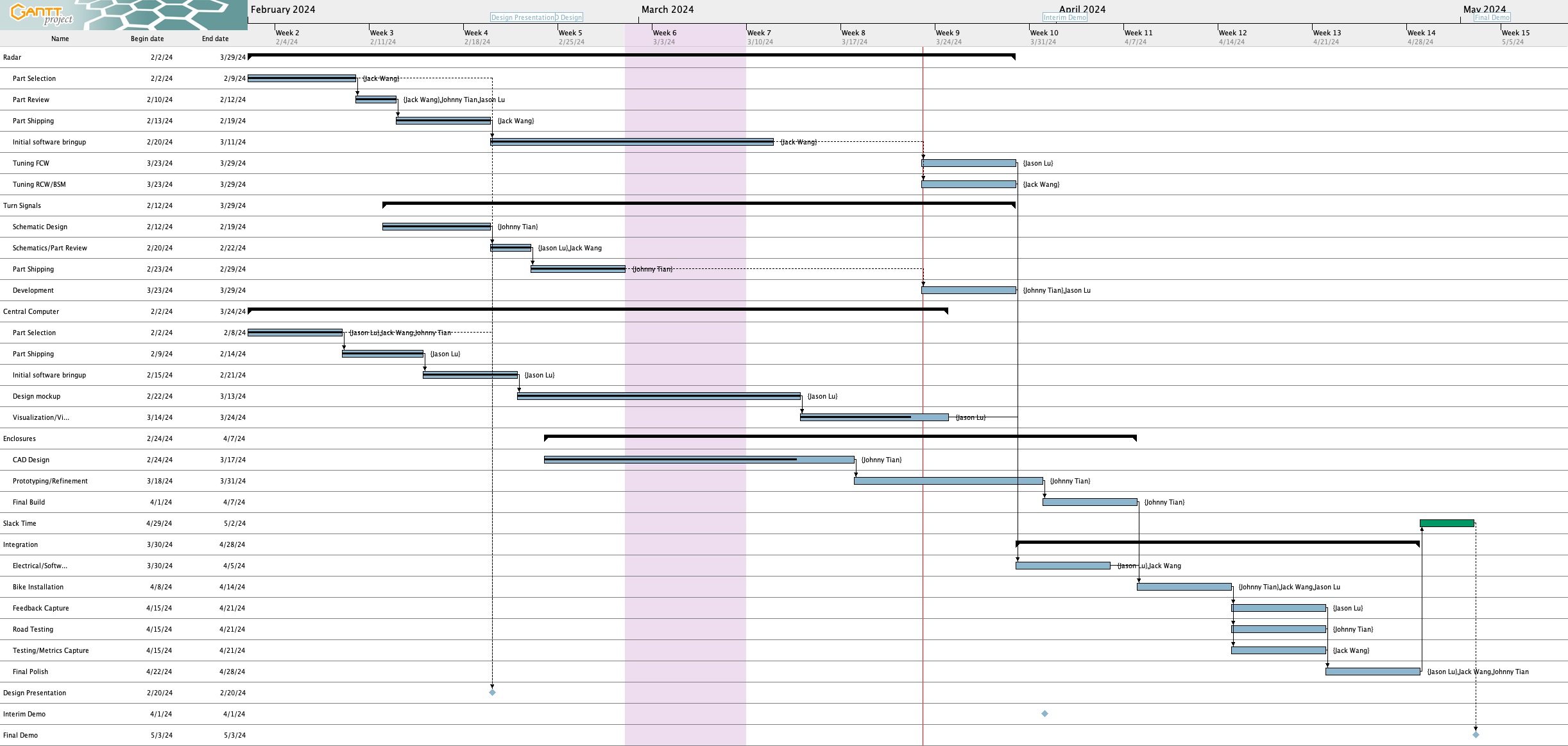
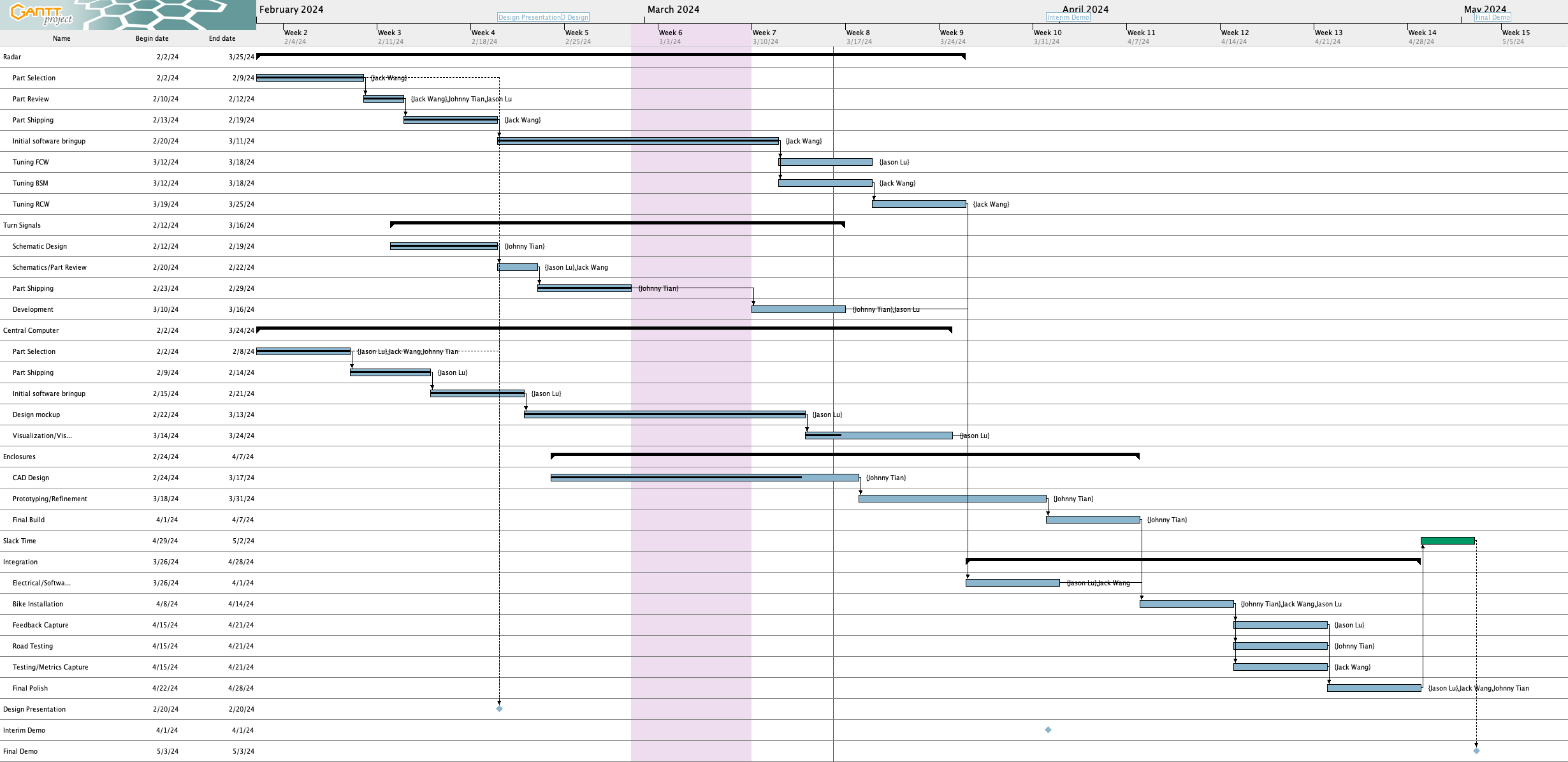
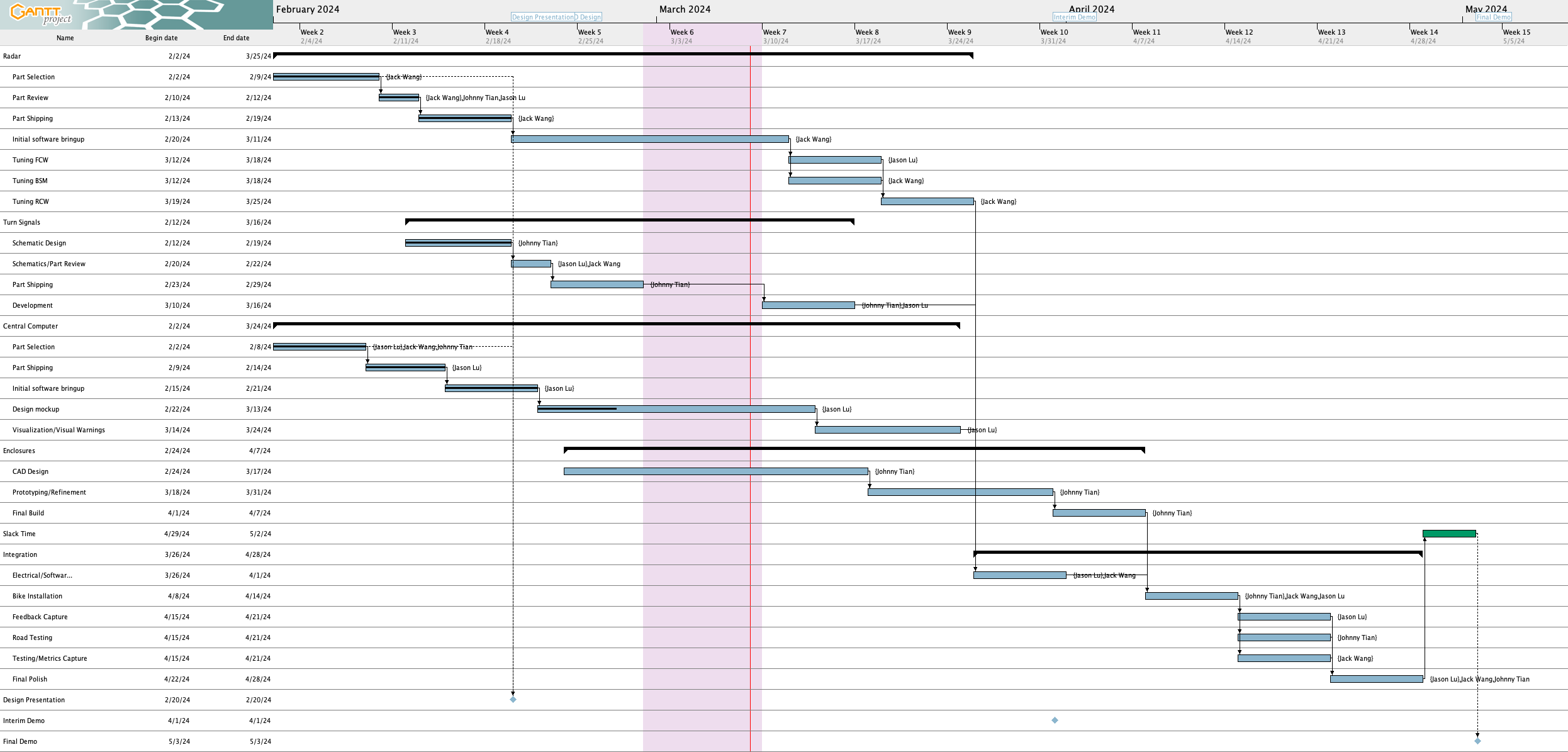
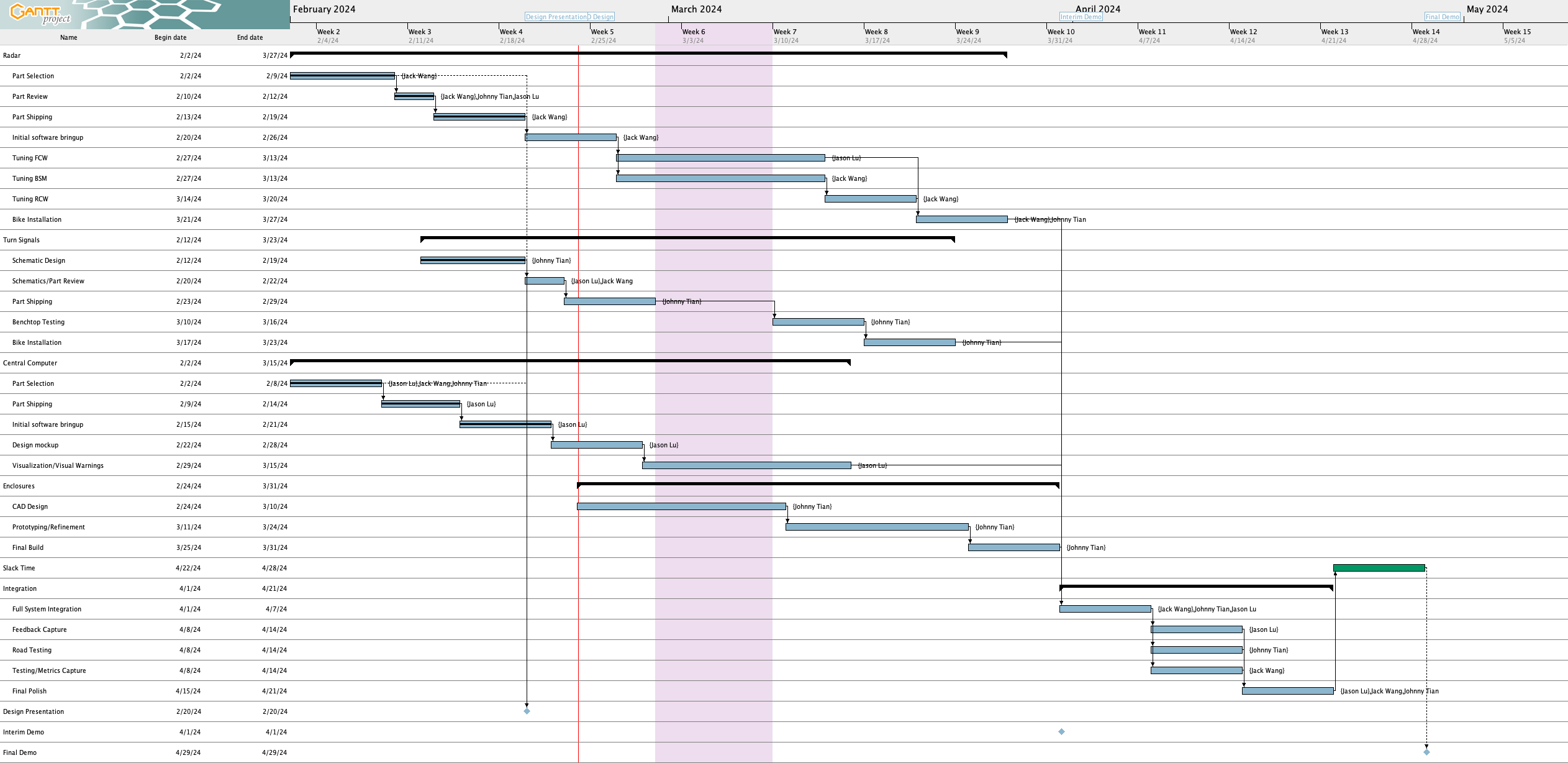
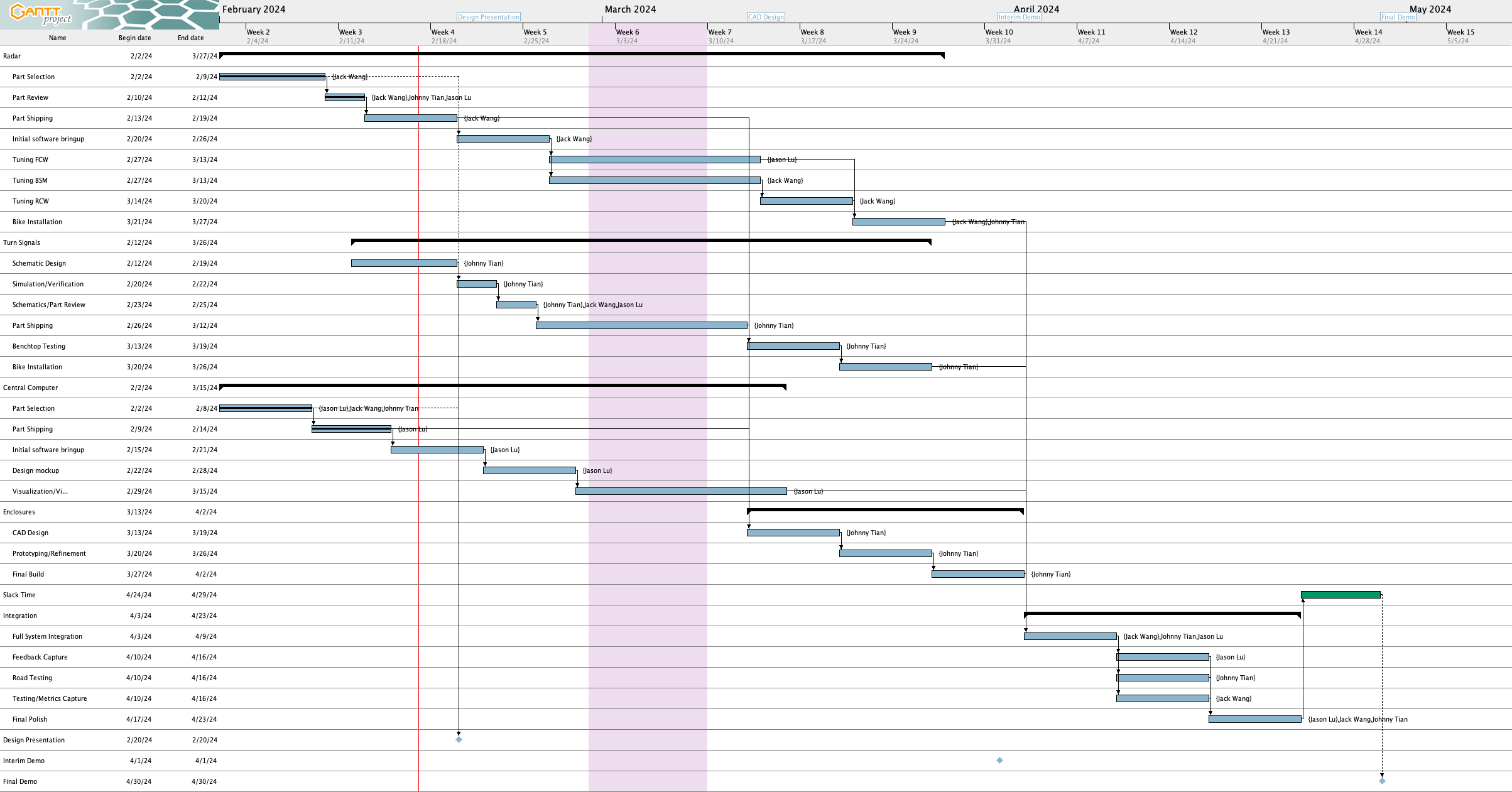
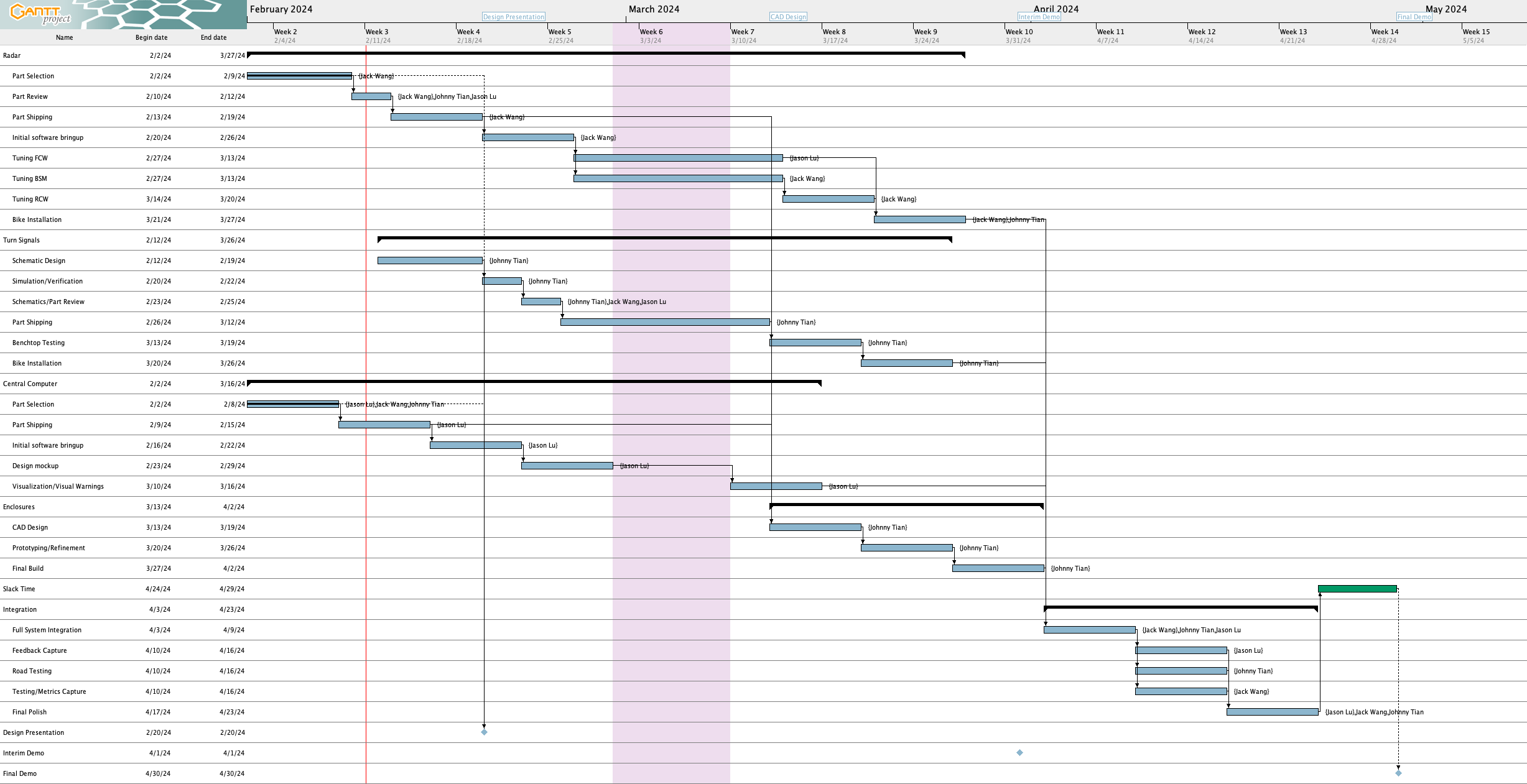
Here’s the Gantt chart as of writing on 4/27:
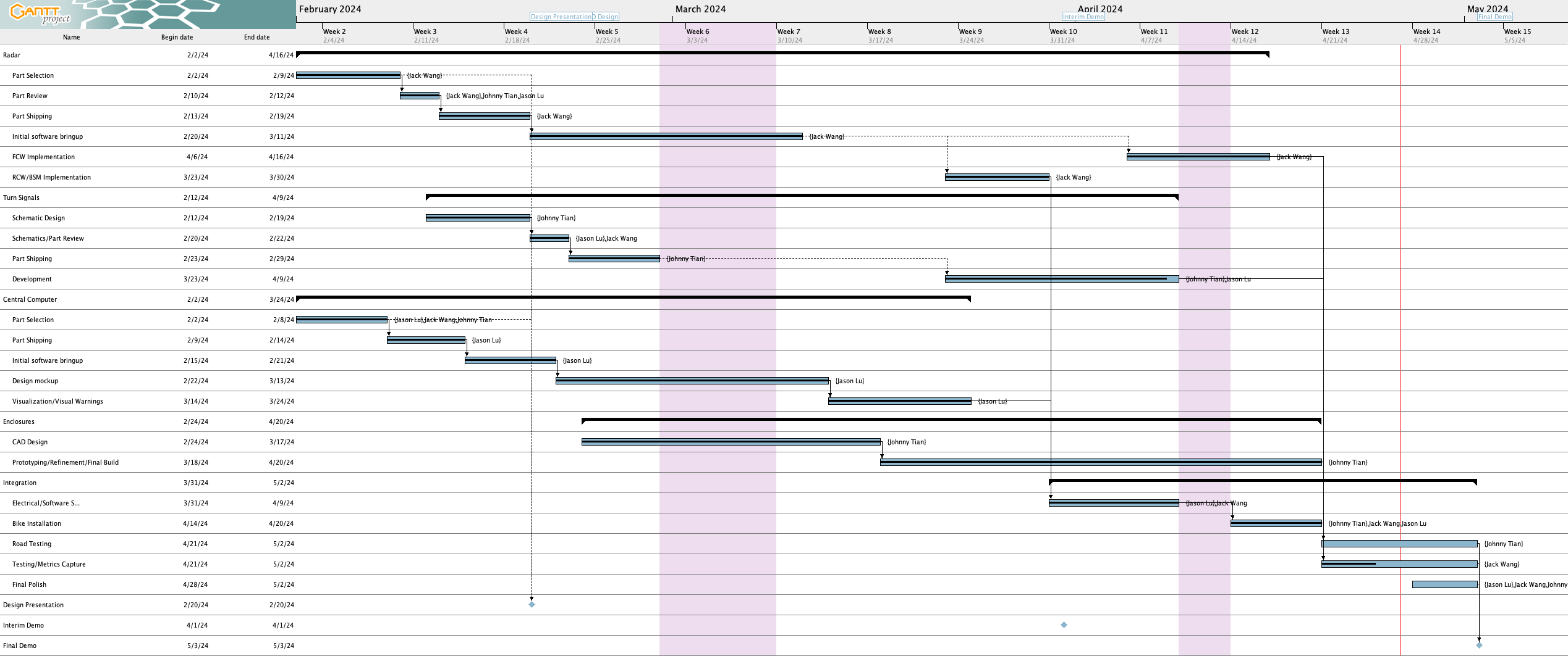
Here are the schedule updates since last week:
Completed tasks 
- Enclosures have all been printed out and installed onto the bicycle (“Prototyping/Refinement/Final Build” task and “Bike Installation” task are complete)
- There was an accident on 4/27 where we broke the left rear turn signal mount due to the bicycle falling over, so that will need to be fixed
Lagging tasks 
The following tasks are behind:
- Turn signal development – Some movement on this the past week, but still not complete – see Jason’s update for more details.
- Road Testing + Testing/Metrics Capture – We are behind on both of these tasks. We haven’t had a chance to take this out onto the road for real world testing. Furthermore, we’ve completed about 35% of the testing we need to do, whereas both tasks are due tonight. Work will have to continue this next week and will therefore run in parallel with final polish
Miscellaneous task changes
- For the “Prototyping/Refinement/Final Build” task and “Bike Installation” task, we are going to exclude sealing the system for waterproofing until as late as possible, as once that happens we will not be able to easily access the internals of the systems.
- Feedback capture task deleted since we’re no longer having ease of installation as a use case requirement anymore
Special Topics
List all unit tests and overall system test carried out for experimentation of the system. List any findings and design changes made from your analysis of test results and other data obtained from the experimentation.
- Power consumption: We have tested the power consumption of the system. The results were 1.64 A peak current draw (which gives us a good idea of the worse case current usage) and 1.14 A average current draw, with the Raspberry Pi’s current draw being mostly responsible for the difference between the peak and average current draw. During the initial tests, we realized that the current going through the transistors was too high which were destroying them (we were pushing more than double the current limit), causing us to change to larger resistors for the LEDs.
- Radar distance: We have conducted some radar tests, including max detection distance to the rear and the side. For the rear, we can detect a car up to 25.14 m on average, whereas on the side (edge of car is 6 feet away from center of bicycle, simulating being in another lane), the range drops to 11.84 m on average which is below our 14 m requirement. Interestingly, the car was actually detected out at 18 m and again around 14 m briefly, which suggests that perhaps the radar is capable of picking the car that far out but we just need to tune the system.
- Turn Signal Range: We were able to test the daytime visibility of the turn signals, reaching a result of > ~112 ft (if measuring using Google maps) or at least 104 ft (since we measured 98 inches of width per parking spot, and there were at least 13 parking spot widths of distance). Either way, this exceeds the 100 ft daytime visibility requirement. We still need to test the night time range. At this moment, no changes are needed.
- Distance Accuracy: This test needs to be redone, but preliminary results show that on average the radar has about a 3% error in its reported distance compared to what we measured using the measuring tape, which is acceptable since it’s under the 10% threshold.
- Velocity Accuracy: This test also needs to be redone, but preliminary results show that on average the radar has about a 7% error in reported velocity, although given the difficult of maintaining a precise speed in a vehicle this may not be that reliable to cite.