update switch connection from 5v to 3.3v since pi gpio are default 3.3V
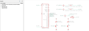
Decide on resistor values
Potentiometer value (P) 20kOhm. Then we have V_divide = 3.3 * R_pot / (R_pot + R_lim). We want to maximize voltage changing rate wrt. R_pot when resistor in middle, which when potentiometer reading (0.5 P) 10k Ohm. Hence we want to maximize first value of the above equation. Then we set R_pot as 10k find first derivative. Then find second derivative wrt. R. Then set the second derivative to 0, which gives us R = 20k will be best. This lead to the center voltage being 1.1V and Max Voltage Read being 1.6V. We will tentativly settle with this. Next week we shall test the noise and the level of accuracy to see if we need to change source from 3.3V to 5V.
Current limiting resistor 20k Ohm for switch just to be sonsistent with current limiting for handle bar position sensor. 3.3V / 20k = 0.165mA => 0.544mW each gpio pin.
Decide transistor model.
Collect CAD file for RPI4 and Lidar and upload to drive (1h)
1. Presentation (6 hrs): Together with Johnny and Jason, we finished the slide deck for the design review presentation. I made the slides about testing metrics and why we chose to use radar instead of other distance-measuring equipment. During lab meeting time, I listened to other teams’ presentations, asking questions and providing feedback. I was able to hear about other people’s projects while reflecting on our project to see what can we improve in terms of hardware and software design.
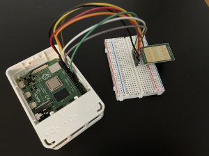
2. Miscellaneous (2 hrs): I set up the team GitHub repo for version control. The link to that repo is omitted here since we are not releasing the source code yet. Johnny, Jason, and I did a quick functionality check with the screen that we purchased. I set up the hardware connection between the K-LD7 radar and the Raspberry Pi using a breadboard. This is not the final setup for our system; it is used for software bring-ups and tests that will be discussed in the next section.
3. Radar Initialization (4 hrs): I began the software bring-up process for the K-LD7 radar. The first phase includes setting up the radar and getting some basic detection results. I did some research on how to get the radar module working with Raspberry Pi and how to get useful output. In the datasheet for K-LD7, I learned the signal processing flow of the module and different parameters such as speed/direction measurement, angle measurement, and distance measurement that we can tune. I discovered a Python API for K-LD7, which is very handy. According to a post from the Raspberry Pi form, RFBeam provided a simple testing script to test the basic functionality of the radar. The script is based on a setup with an evaluation kit. I modified the script to make it work with Raspberry Pi. However, until the time of the blog post, I have not tested the radar setup yet. This will be done before the team meets on Monday.
Progress:
I am still on schedule, but running tight on time. The radar bring-up was started this week. However, it was delayed a bit due to the later-than-scheduled arrival of the radar module. The deadline for the software bring-up is this coming Monday. However, given the current progress, I might not be able to fully test the software functionality of the module, although the basic initiation will be completed by the deadline. To solve this matter, I will prioritize solving issues related to radar software bring-up next week. We have some slack time during spring break as well, so I still have some buffer to fix any remaining issues without disrupting the main schedule. Overall, the work on the radar is still going as planned.
Next Week:
Finish radar software bring-up
Simple radar detection tests
Varying parameters to see how the results change.
Deliverables: We should be able to get some serial outputs from the radar on some basic detection. The output should be displayed using pyserial. We should also have a better sense of how to use this radar module in general, and what will be our challenges in this phase.
Software bring-ups: We have received all the parts that are needed for this phase of the project. We have dedicated this time in the schedule to do some initial software bring-ups and tests. For example, we need to make sure that the radar will produce the data that will work with our system; finding a suitable framework is another thing that we are working on. These are risk factors because even though we have dedicated time to do the initial bootstrapping, we might run into different situations along the way that will delay the project. Working with software is unpredictable, especially for a project like this. In addition, although each component might work at this stage, the integrating results are still pending. So we still run into the risk of things not working later on in the pipeline. We are managing these risks by doing careful research and making sure we have slack time and backup plans when things go off. For instance, Jason has done a wonderful job of looking into the best UI framework for our purpose. You can see more details on his status report this week. Jack searched for previous usage of K-LD7 radars with Raspberry Pis, trying to avoid issues that people ran into before. He was able to find some useful information for processing data. You can see more on his status report.
Hardware designs: Johnny had some amazing ideas for the design of the enclosing box. However, as we ordered the other components, we might need to readjust the hardware design ideas we had in mind to fulfill the shape and size of those components. We have some risks on the timeline for the enclosure and mounting issues because it might be a bit more complex than what we originally expected. We will mitigate this by moving the design timeline up and extending the time available for designing the enclosures. Please see the schedule updates section for more details.
We also changed the power to the turn signal auto-cancellation system to use 3.3V as the high side input from the Pi, not 5V due to 3.3V being the max GPIO voltage (link 1, link 2)
We also need to source an ADC converter with I2C communication, since the PI gpio doesn’t have analog input.
Schedule Updates
Here are the updates to the schedule from last week:
The Verification/Simulation step for turn signals has been deleted, since the circuits seem simple enough that we can skip that step
This change is motivated by the fact that we’re behind and this step seems non-essential
The CAD design start date for the enclosures has been moved up to today (from 3/13), and the time for prototyping/refining the enclosures has been extended to two weeks
There are some concerns that the original allocated time may not be enough since the things we need to build appear complex, so we wanted to move it up to get more time to work on it
Total slack time has increased from 5 days to 7 days
We are currently behind on the turn signal stuff due to incomplete schematic review, although we may be able to catch up by obtaining parts from ECE stock. On other aspects, we are currently on track.
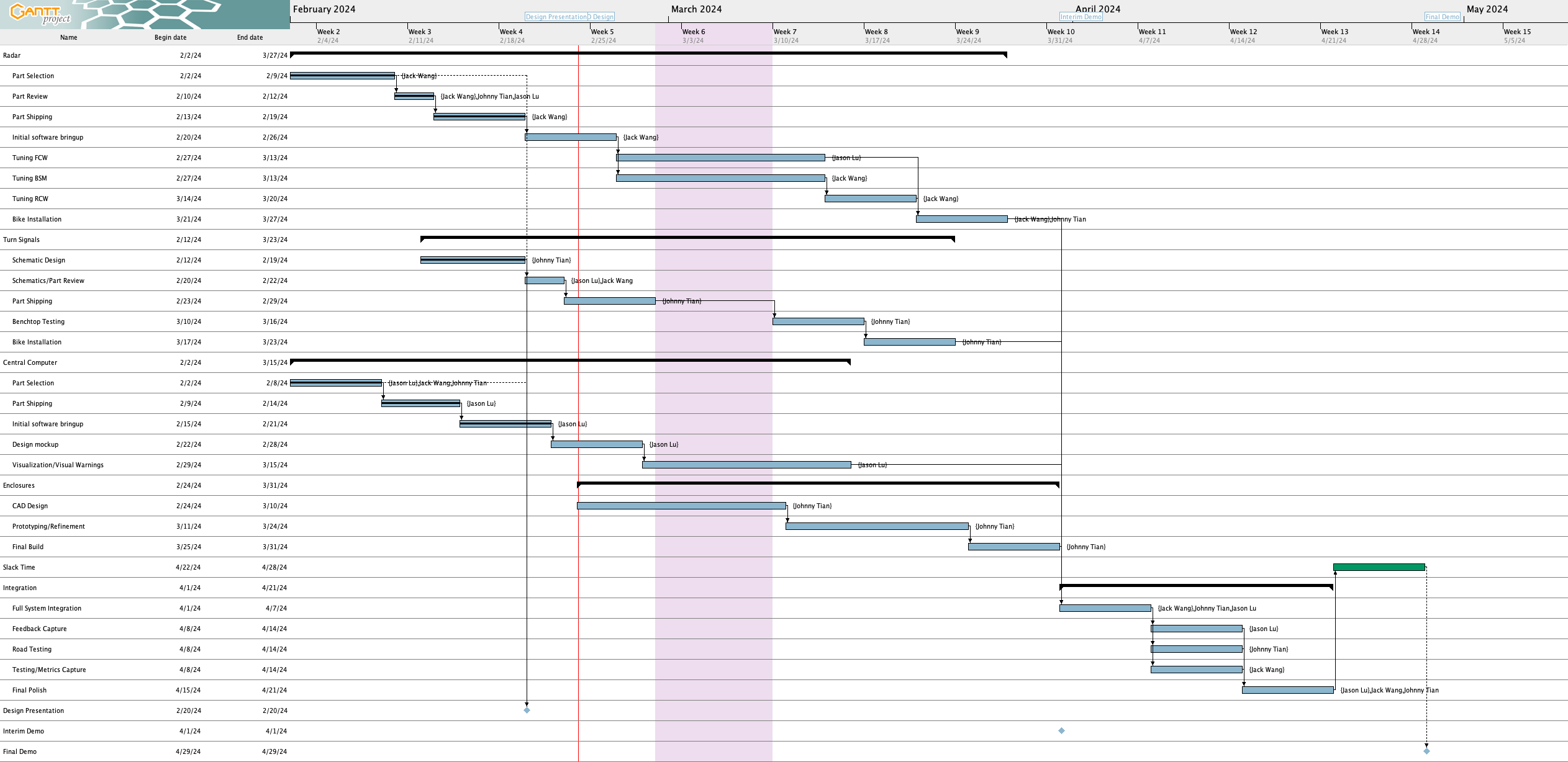
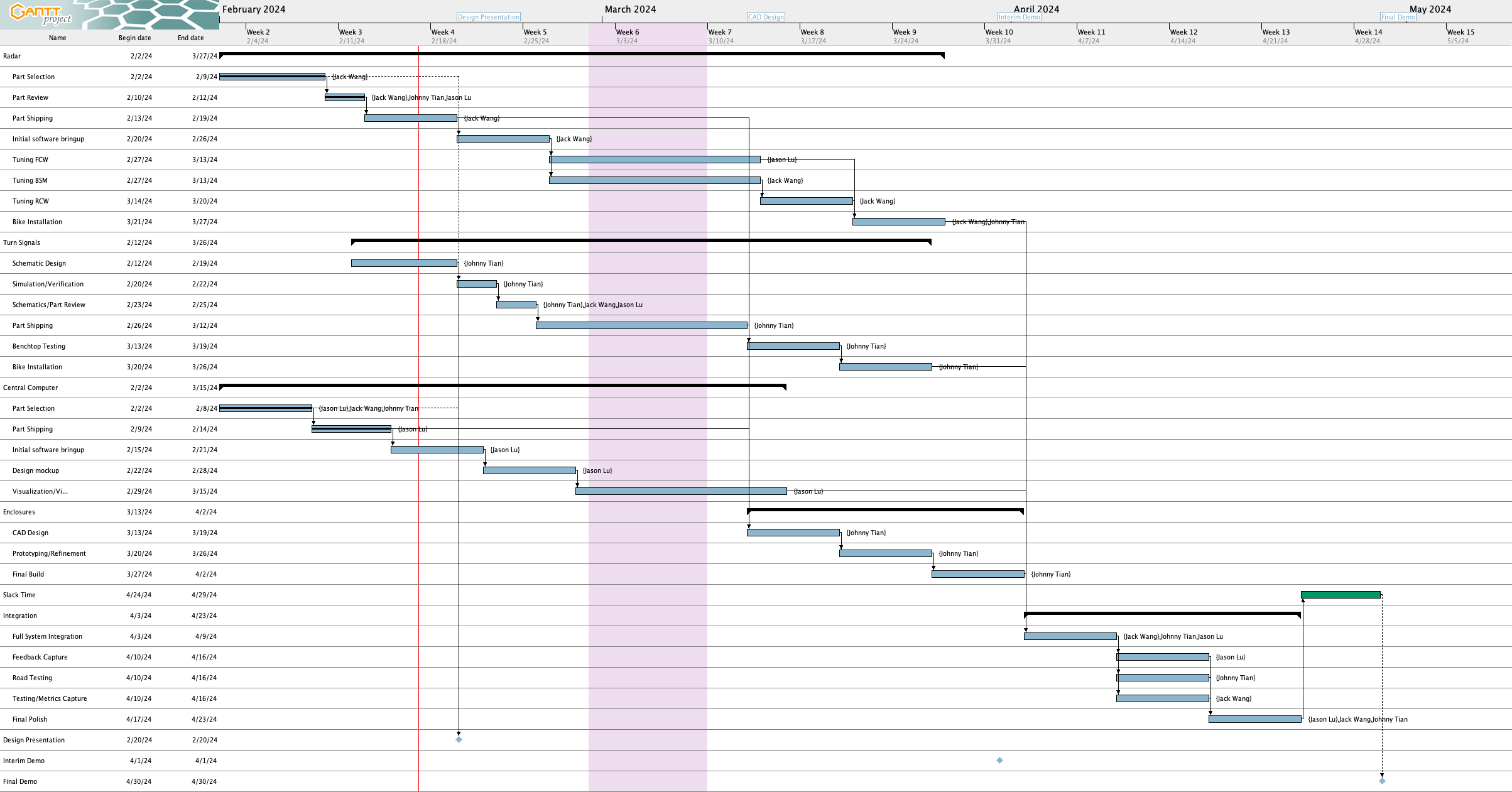
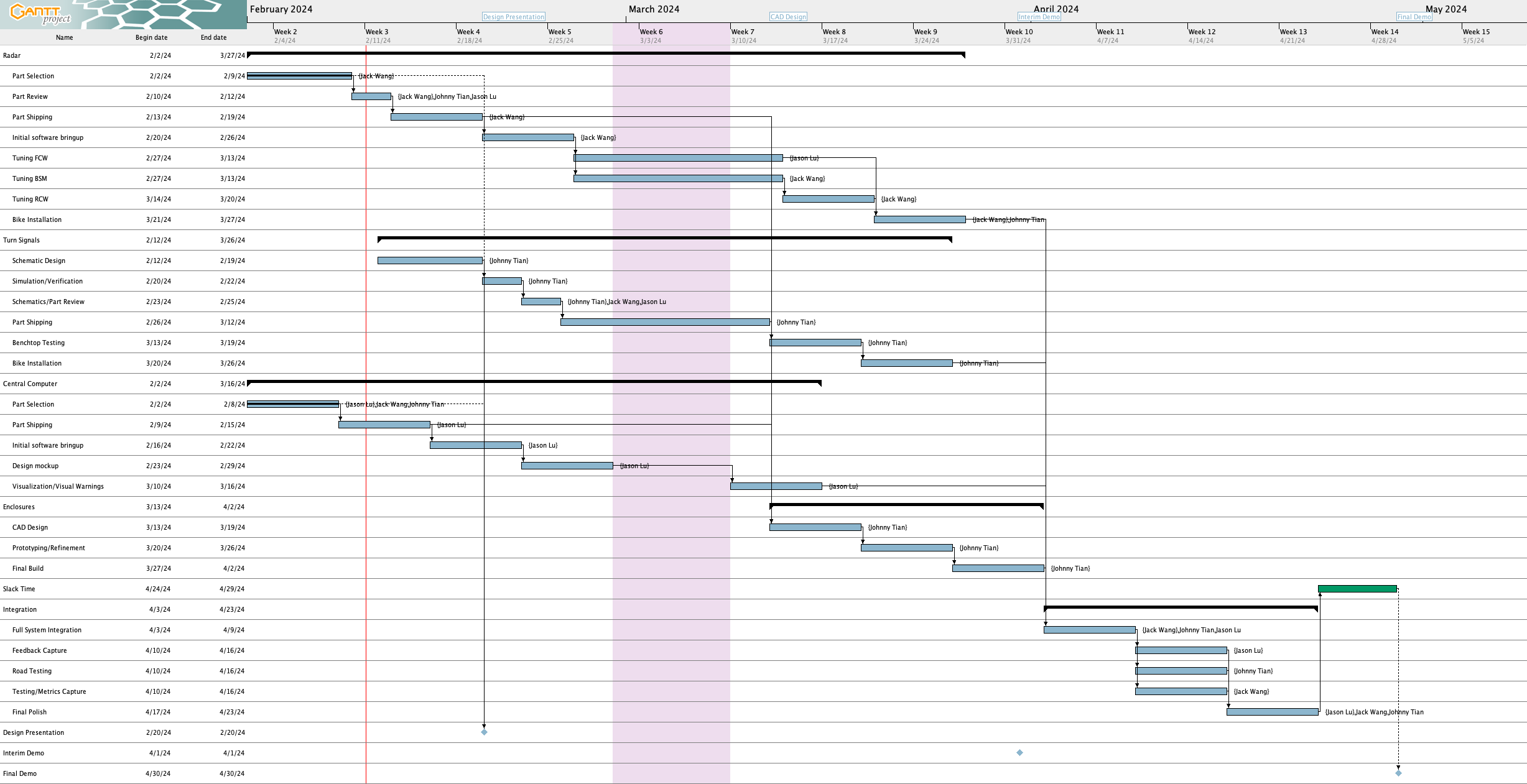
Updated Gantt chart for this week (click for a larger image)
Flashed firmware for the Pi – whatever was on the Pi originally did not want to boot
Chose a UI framework (see below)
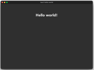
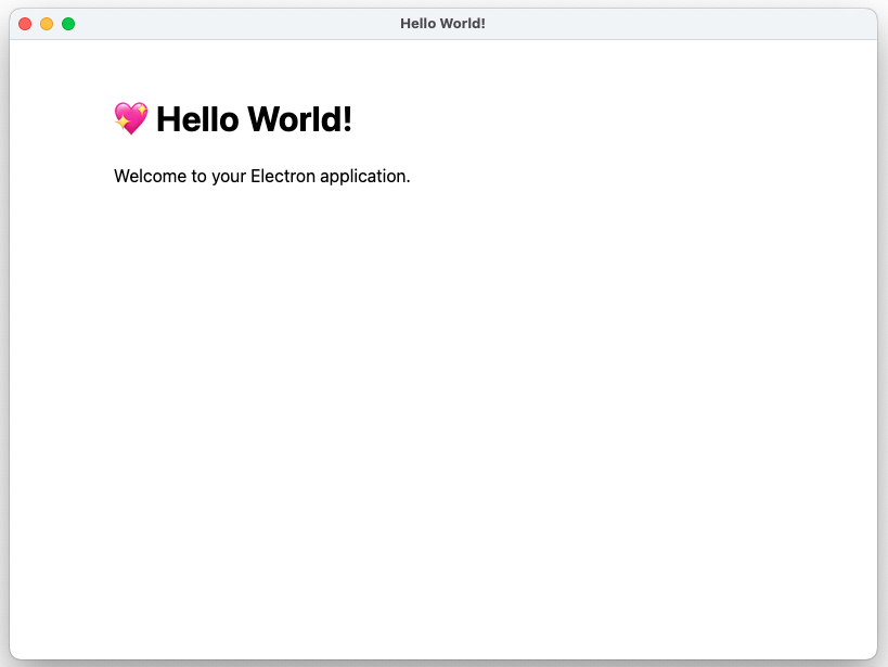
Built a hello world app in Electron (see below)
Schedule
Out of the 5 targets from last week, I’ve completed 4 of them (green text).
Complete the design review slides
Get the RPi up and running
Select a graphical framework
Write a barebones hello world GUI application
Begin UI mockup
I originally slipped behind a bit according to the schedule as software bringup was supposed to be done by 02/21 and I only finished it on 02/24. Nonetheless, I am on schedule as of this moment again, although there is a risk of slipping behind a bit if I don’t finish the UI mockup by 02/28.
Upcoming Deliverables
The main deliverables for this week are:
Complete the UI mockup by 02/28
Start implementation of the UI in code
Choosing a UI framework
Step 1: Options
I ruled out using a web app simply because we would need to interface with hardware which is more difficult with web apps. I’d need to write native code even with a web app to interface with the hardware, and trying to connect the native code and web app seems difficult to me.
Here are some options that I first considered:
Electron – I knew of this as a cross-platform UI framework that uses Chromium under the hood
During testing, I also added a Rust framework that is conceptually similar to Electron, called Tauri. I’ve seen it before in my free time and I saw it again when I was browsing Rust UI frameworks at https://areweguiyet.com/. I chose to add it because I saw the high memory usage of Electron and wanted something conceptually similar but hopefully lower usage, and I was curious if Tauri might accomplish that.
Step 2: Evaluation Criteria
Here are the criteria that I used to evaluate things. Note that not every factor is weighted equally.
Cross-platform – Can this run on both MacOS and Linux? Our RPi runs Raspbian, and I plan to primarily develop on my MacBook so if the framework is cross-platform I can work on my MacBook and build for Linux from the same code base.
Language/Tooling Familiarity – Given that we have limited time for developing things, I don’t want to spend too much time on learning the language primarily used for the framework nor learning how to use the framework itself.
Adoption – Who are the major users of it? If it is a framework that is used by major apps, it means that this framework should be production-ready and is proven to be usable for real-world tasks.
Baseline resource usage – How much CPU usage and RAM do we use rendering roughly the same things? Our Raspberry Pi 4, while it does have 8 GB RAM, at the end of the day is more of an embedded system that does not have the power of a desktop system. Spending too much resources on rendering the UI would increase power draw and take up performance that could be used for other tasks like radar data processing and collision time estimation.
Cross-compileable – Can we easily build packages for the RPi 4 from a host computer? While technically I could build on the RPi 4, it’s easier to build on the host computer and copy the package to the RPi 4 so we don’t have to install build tools on the Pi itself. Building on a laptop is probably a lot faster too.
Step 3: Testing
I created hello world apps in all 4 frameworks and measured their memory and CPU usage. Testing was conducted on a M1 MacBook Air running MacOS Sonoma (14.2.1) with 16 GB RAM. Admittedly the laptop is much faster than an RPi 4 and isn’t even running the same OS, but I’m hoping that the general trends will be similar across MacOS and Linux.
The memory usage was obtained by using Activity Monitor and summing up the relevant threads’ memory usage (e.g., for Electron we have multiple threads running around so we need to account for all of them). For calculating CPU usage, this is admittedly a lot less scientific where I just watched the CPU usage of the threads and grabbed the maximum value (only if it repeatedly hit it – e.g., hitting 1% CPU usage just once wouldn’t count, only if it fluctuated up to 1% a few times).
The code for all of four demo applications are in our shared Github repository.
Here are some screenshots of the hello world apps:
“Hello world” using Electron“Hello world” using QT“Hello world” using GTK“Hello world” using Tauri
Step 4: Decision
All four frameworks are cross-platform so we can ignore that as a deciding factor, although if one of them wasn’t it would have been a major negative point.
For Tauri, I was unfortunately unable to find any applications that I knew of that used it, which made me a little more hesitant about whether it would be as production-ready and usable for real-world apps as the other three. Therefore, I ruled out considering it further.
Between Qt, Gtk, and Electron, Qt and Gtk have similar performance requirements. Sadly, Electron uses 5x the memory and has a little bit more measurable overhead.
However, I feel much more comfortable with using HTML/CSS/JavaScript for building UIs since I’ve used them before for web development. In contrast, I’m not as familiar with how to build UIs with Qt and Gtk (either through code or the GtkBuilder system) which would take additional time to become familiar with. I also was not familiar with Qt’s tooling such as Qt Creator (although apparently it isn’t required, just recommended), so learning that would incur some additional time expense. Language-wise, I feel more comfortable with Javascript/HTML/CSS or C vs. C++. So overall, I feel a lot more comfortable using Electron compared to the other two due to the smaller learning curve.
So in the end, it is a tradeoff between performance overhead and ease-of-development.
Given that consideration, I’d rather use Electron despite the performance overhead simply because the lower learning curve is more important to me. The memory usage, despite being 5x as much, shouldn’t be an issue on the Pi when we have 8 GB (although it will make it more difficult to downsize to a board with less RAM). The fact that Electron can be easily packaged for Linux from MacOS is a bonus whereas packaging the other two from MacOS will be harder (see references).
DECISION: Use Electron for the framework
Building a Hello World App
Scaffolding
First, I had to scaffold a basic Electron app. Based on the Electron tutorial which mentioned the create-electron-app command, I decided to use that so I didn’t have to spend time on boilerplate stuff.
Reading the documentation for create-electron-app, I saw I had a choice between Webpack and Vite-based templates. I’ve used Webpack in the past but Vite was completely unfamiliar to me, but based on https://vitejs.dev/guide/why and https://blog.replit.com/vite it seems like it does the job of Webpack (although not all of it) so I’ll go with that. TypeScript is nice because it gives us typing information, so I’ll use the vite-typescript template.
Screenshot of the app that was generated using create-electron-app
Testing Packaging
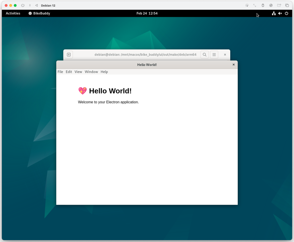
I also wanted to see if I could package this for a Linux system. I spun up an ARM Linux image on my computer (using UTM and the Debian 12 image from UTM), and built a .deb package for Debian using electron-forge. After installing it, I verified I can build packages for Linux from my Mac and have it run!
A screenshot of BikeBuddy packaged on MacOS running in a Linux VM
Worked on the design review slides along with my team
I developed a block diagram for our system:
Since we were planning to use a power bank, I wanted to to figure out if USB negotiation is needed for higher power. Decision: No need for negotiation, see power allocation
However, this Sparkfun USB-C breakout allows 1.5 A up to 3 A. After reading the schematic for that and the USB-C datasheet, I found out that breakout board has resistors that allow for a higher current
From the K-LD7 datasheet, we know that the K-LD7 draws up to 200 mA peak (so 400 mA total for two radars)
Researched how to connect multiple wires together (without a PCB or breadboard) since we plan to directly wire the battery pack to the radars, lights, and potentiometer circuit. Decision: Go with wire nuts
My original idea was to solder things, but I got spooked by this Reddit post which talked about solder melting, although in hindsight it was talking about code compliance which doesn’t apply to us and house wiring (we won’t be pulling that much current)
Then I remembered that at work I’ve used wire nuts before, so I wondered about using wire nuts to tie them all together (I forgot that they were called that so I had to Google “twist on wire connectors” lol)
Another Stack Exchange answer and this post (see step 3 photo) indicated that wire nuts are a valid way to connect things together
Othersourcessuggested using terminal blocks/strips (where strips are multiple blocks combined) or butt splices, but I either couldn’t verify that they would work since I’ve never used them (like this WAGO connector), looked to be expensive from a first search on Digikey although later sorting showed < $12 ones (although $12 is pretty expensive still compared to wire nuts), or I didn’t want to deal with trying to bridge together the terminals with jumpers/special pieces of metal as the answers suggested
Schedule
Out of the 4 deliverables from last week, I only met one (green = completed, red = incomplete). However, I’m still on schedule as I have until 02/21 to complete initial software bringup and I plan to test the Pi and start software bringup this week.
Get the RPi up and running
Select a graphical framework
Write a barebones hello world GUI application
Select and order a display to attach to the RPi (done with team)
1. Parts: The quality of parts remains the biggest risk at this stage of the project. We have done a lot of research on the components that are required for BikeBuddy, and we made decisions based on documentation and logical reasoning. However, a part that looks good on paper may not perform the way we want it in reality. For example, the turn switches that we purchased did not meet our expectations, where the switches need to be toggled to both turn on and off. This was just a small part of the project, so our contingency plan was to revert to a simple button instead of a fancy turn switch. However, this could be a huge issue if it happens on more time-critical parts like radar. Until we check out all the parts and make sure they are compatible with each other, this remains our biggest risk. We hope that our careful research for each part will mitigate such risk. However, we have backup parts that can be ordered if our original parts do not work out.
2. Scheduling: In our schedule, we left one-week time for the parts to be shipped. However, the unpredictable shipping speed is another risk that can pull us into schedule issues. The radar is taking a bit longer than we expected to arrive. If a part takes a significant amount of time to arrive, it might lead to a knock-on delay in our progress. To mitigate this, we still have slack time that we can use to smooth things out. We will follow up with the shipping status so that we know if we need to order new parts as backups.
Changes in Design
We’ve altered the requirement from being portable to simply being easy to install. We realized that we wouldn’t expect the end user to need to frequently move our safety system around so the portability requirement wasn’t necessary. However, we would still like this system to be easy to install hence the change in requirement.
The motorcycle turn switch we bought turned out not to be what we wanted as the switch didn’t return to the neutral position when activated, rendering our turn signal auto-cancellation system useless. Other turn switches on Amazon (some include example 1, example 2) seemed to have the same issue where the turn signal switch is latching which wouldn’t work for our case. In hindsight, that actually makes sense as how would the turn signal know to deactivate automatically on a motorcycle without being able to sense the handlebar position? Therefore, we pivoted to using motorcycle momentary button switches to activate the turn signal, such as this switch.
The wiring diagrams such as the ones listed here indicate that the button shorts the two inputs together which should work for us as a GPIO input into the Raspberry Pi to sense a button press (e.g., put 5V on one side of the switch, on the RPi side have a pulldown to ground).
We’ve settled on choices for several of our components:
Screen choice of a 5″ HDMI screen – We wanted a screen that used HDMI to simplify the interface with the Raspberry Pi (unlike other ones that used raw RGB data!) and this screen met that requirement.
There was some concern about whether this would be sunlight visible, but we weren’t able to find a screen that was bright enough, yet cheap and used HDMI (somesources said 1000 nits or 800 nits – I recall seeing 700 nits somewhere but can’t locate the source now :/). The decision we ended up with was that it looked bright enough in photos so we’ll try out this screen and worst case we’ll put a shade/visor over it.
We selected the 5″ over the 7″ one because we felt that the 7″ was unnecessarily large.
The current draw is acceptable for our use case (the 7″ screen states 0.62 A draw) which is able to be supplied from the RPi 4 which has a 1.2 A USB limit
Radar choice of the K-LD7 – According to its product page and datasheet, it supports up to 30 m range for car detection which is more than we need, it mentions blind spot detection as a use case which gives us more confidence that this will work for that, and it performs on board signal processing and gives serial output instead of raw sinusoidal data which simplifies the work we need on our end. The current draw is also minimal (200 mA peak) according to the datasheet.
Battery system of the Anker 337 – Initially suggested by Professor Tamal, we settled with this one because it was capable of 3A output on each USB port which was recommended for powering the Pi 4 and output 5V which was what everything we used ran off of. Additionally, the capacity was very large.
We’ve created an initial block diagram of the system as well:
Schedule Updates
There have been no schedule updates since last week and things are currently on track.
Here is the Gantt chart as of Feb. 17, 2024 (click for a full-sized view):
Weekly Special Questions
Note: Part A was written by Jonny Tian, Part B was written by Jack Wang, and Part C was written by Jason Lu
A. Public health and safety
Incorporating our project into bicycle design helps mitigate the risk of accidents and promotes overall road safety. Blind spot monitoring systems alert cyclists to potential dangers, reducing the likelihood of collisions with vehicles or pedestrians. This not only protects the individual cyclist but also contributes to the broader public health by minimizing the occurrence of accidents. Additionally, turn signals on bicycles enhance communication between cyclists and other road users, promoting a more predictable and organized flow of traffic. This increased visibility and communication can prevent misunderstandings, reducing the overall risk of accidents and creating a safer environment for all road users.
B. Social factors
Our project will primarily target the social group of urban cyclists and motorists who share the roads in densely populated areas. BikeBuddy is designed so that people from this cohort can afford this product and enhance their safety in their day-to-day lives. This group of people rely on bicycles or share the road with cyclists. The system that we are offering such as the blind spot detection and display addresses the critical need for improved awareness of surrounding traffic, particularly in urban environments for this group of people. In addition, our solution to enhanced bike safety will also promote a safer cycling environment, encouraging more people who rely on bikes to cycle more. Since the design is modular and has user-friendly interfaces, the system can be accessible to a wide range of cyclists. Overall, our system considers the core needs of this group of people, offering inclusivity and equitable access to safer cycling experiences.
C. Economic factors
Our target price point of less than < $200 was intended to make this affordable for regular commuters who may not be willing to spend as much on a safety system instead of for professionals who have deeper pockets. As a result, we didn’t use arguably better systems such as the TI series of automotive radars which are specially designed for the blind spot monitoring use case in vehicles but are significantly more expensive to use (ex: one EVK for a TI radar cost $358 from Digikey).
Admittedly, at this point, we’re not certain if we can hit the price target, but one hope is that if we calculate the cost to consumer using the bulk pricing then that target will be feasible. For example, we are currently buying radars for around $86 per unit since we are buying small quantities, but if this is commercialized and we buy larger quantities for production (e.g., hundreds) we can bring it down to ~$65 per radar.
The requirement of being easy to install (which we changed from being portable) also means that the end user should not require specialized equipment or need to go to a bike shop to install the system which further reduces the cost of obtaining this product.
We also do not anticipate significant operating costs to the end user with the exception of electricity bills from charging the battery pack, so there should not be a long term economic burden to the user. The intended ruggedness of the system also should ensure that the system won’t need replacing too quickly which would be expensive.
On a macroeconomic level, another thought we had was that this could reduce total healthcare and vehicle repair costs. If we lower collision rates between vehicles and cyclists, we reduce the number of hospital visits needed for cyclists and the repairs needed to repair vehicles damaged in collisions which will hopefully result in an overall reduced average cost to cyclists and drivers alike (e.g., expected value of repair costs will go down because the probability of a repair being needed is reduced).
Lab Meetings (4 hrs): With my team members, I finalized the BOM of the project, especially the choice of radar. We have discussed the benefit of the K-LD7 radar based on the datasheet. It provides us with the range that we need, along with a nice serial output that is easy for us to process. I have also identified a Python driver for the radar to help us process the output data of the radar. The radar and the other components were ordered. During the lab meeting, we presented our ideas to Prof. Fedder and the TA, where we received the acknowledgment of the radar choice.
Presentation Prep (4 hrs): Together with my teammates, I prepared the design review presentation. Please see here for more details on our presentation. I am mainly in charge of the design requirements, radar, and testing slides.
Project Meetings (4 hrs): I discussed the power source of our project with Jonny, and with the help of Prof. Mukherjee, we decided to use a large enough power bank as the power source. I researched the requirements for using radar frequency bands based on the FCC regulations. I also reached out to Prof. Sullivan to confirm the regulations. I also tested our LED blinker with Jonny.
This is a major risk for the project at this time because the parts are the foundation of the project. The risk lies in the discrepancies between the advertisement online and the actual product. If the product comes in as not what we are expecting, this could cause delays to our schedule and alter our plans.
We are mitigating these risks by asking people who are familiar with the parts that we are looking for, hoping for a more accurate review. We also plan to order more quantity than needed for each component in case there are manufacturing issues. In addition to the parts that we want, we also have several backup plans that we can order quickly.
2. Integration:
We need to make sure that each part that we plan will integrate properly with others. It might look good on paper, but the actual integration of HW and SW is challenging. We risk taking longer than expected time to solve those issues. These risks are managed by having slack time to troubleshoot the issue.
Changes in Design
No more 9V battery pack, use normal power bank instead since most of our components use 5V
Benefits:
Eliminates need for DC voltage converter
Easier to find off the shelf parts, or people can just use their own power bank
Drawbacks:
Need to design our own tail light to fit 5V power source
Settled on RPi 4 for main embedded system
We felt that the performance uplift of the RPi 5 (2 – 3x) was unnecessary for our project when the RPi 4 might provide enough performance at a lower power draw (both idle, under load, and peak power usage)
Schedule Updates
There as been an adjustment to the start date from 02/02 to 02/12 for the turn signal schematic design to give Johnny more time to work on it. This pushes back the start of the CAD design for the enclosures which in turn pushes back the integration date and reduces our slack time to .
We are exploring whether we can do the enclosure design in parallel with the turn signal design so we can move the integration date back up again.
Presentation (4 hrs): Together with my teammates, I prepared and presented the proposal presentation on Monday. Please see here for more details on our presentation.
Lab Meetings (4 hrs): I listened to other teams’ proposal presentations during lab sessions, asking questions and providing feedback. I was able to hear about other people’s projects while reflecting on our project to see what can we improve.
Project Meetings (4 hrs): I met with my teammates outside the mandatory lab meetings and discussed the bill of materials (BOM) for our project. I spent time researching possible radar modules that we can use to do blind spot detections. As of the time of the post, I have narrowed down the choices to two radars (K-LD7 & HB100). I will continue to discuss with my teammates to make a final decision.
Progress:
My progress is on schedule so far.
Next Week:
Review and finalize parts on our BOM.
Review the documentation for the radar that we choose and search for compatible libraries if needed.