Risk and Plans
Although we are making good progress in integrating the system, unexpected problems are popping up, which might jeopardize our plan. At the final stage of the project, unexpected delays remain the biggest risk that we need to mitigate. Much of the mitigation of the last-minute delays has already been in place throughout the project. We made sure each component functions as desired and have plans on how to integrate them. However, we could not predict everything, as in every other engineering project. For example, we found the dimensions of the 3D-printed parts were slightly off. This meant that it would take us extra time to fix the issues, increasing the risk of running over the project deadline. We can mitigate this because we intentionally have not planned a lot of work for each member, other than integration, during the final phase of the project. So when an issue arises, the entire team can focus on addressing the issues and solving them more efficiently. We also make sure that we have a priority list of items that need to be working for our MVP, which allows us to address more important issues first when challenges come. With such planning, we hope that the chances of running over time are low as we still have some slack time for the project.
Changes in Design
No changes to design.
Schedule Updates
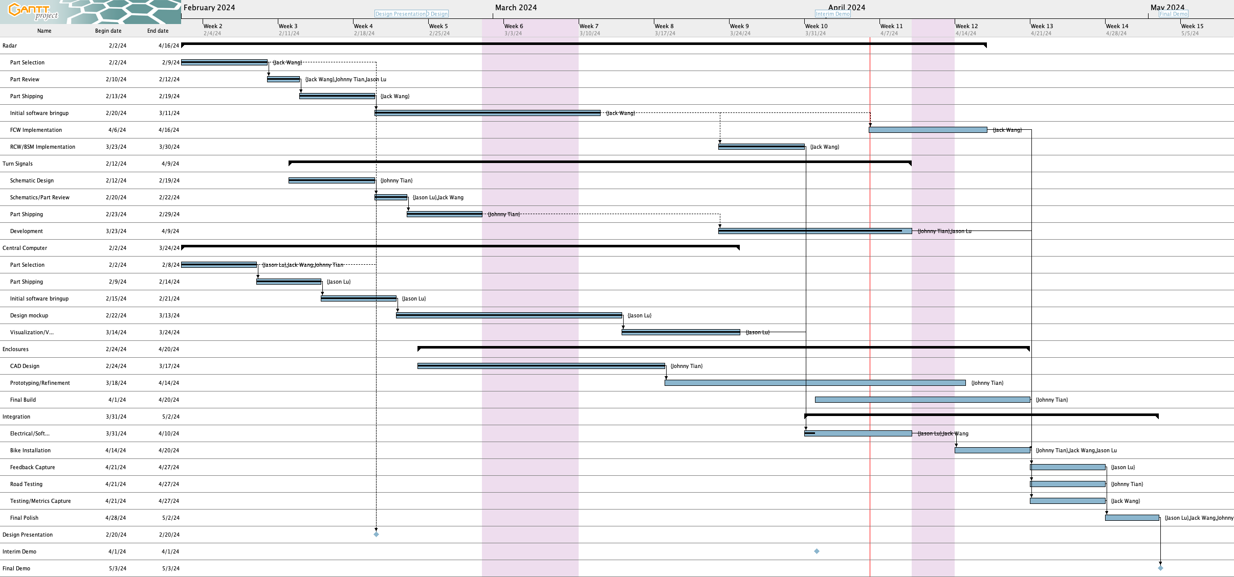
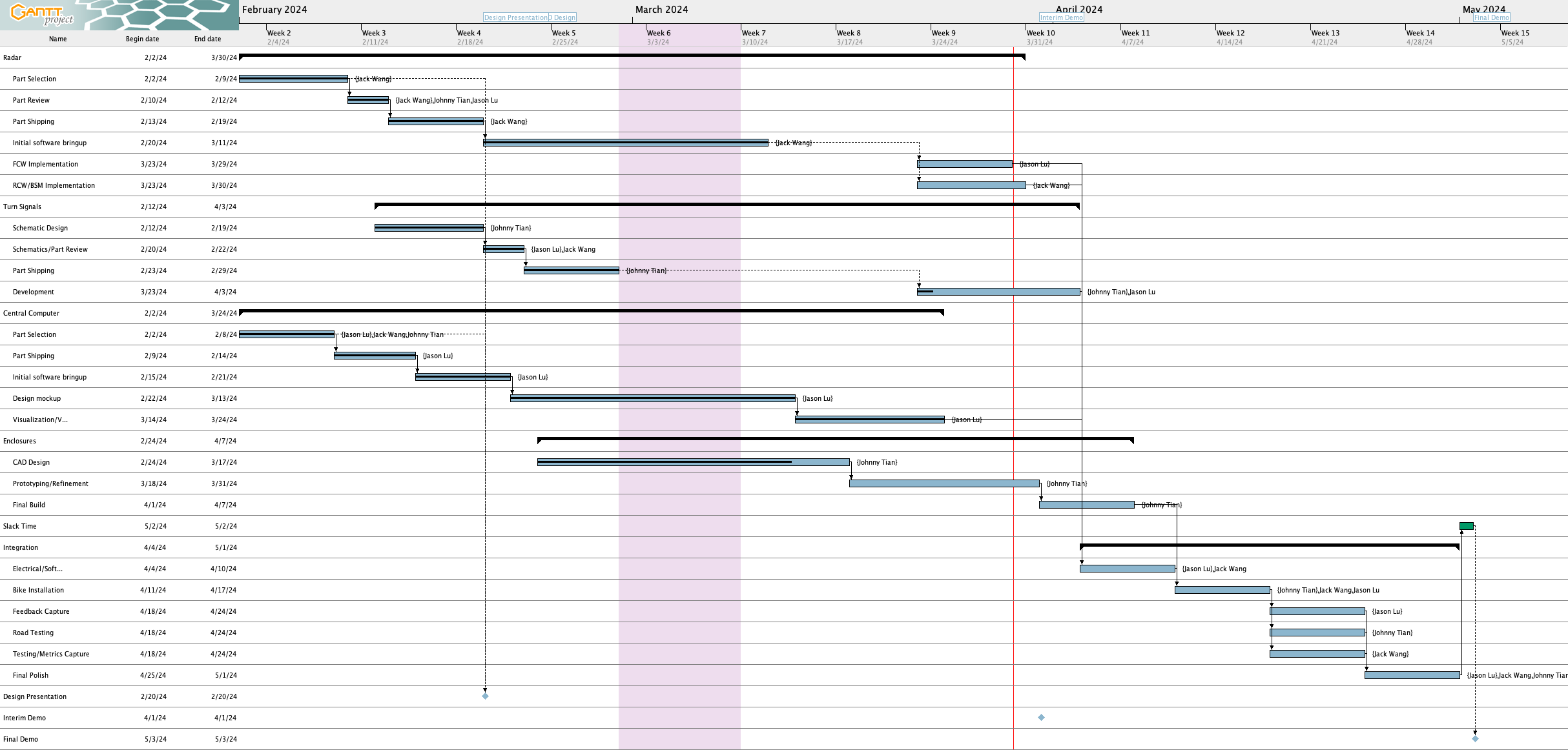
Here’s the Gantt chart as of writing on 4/20:
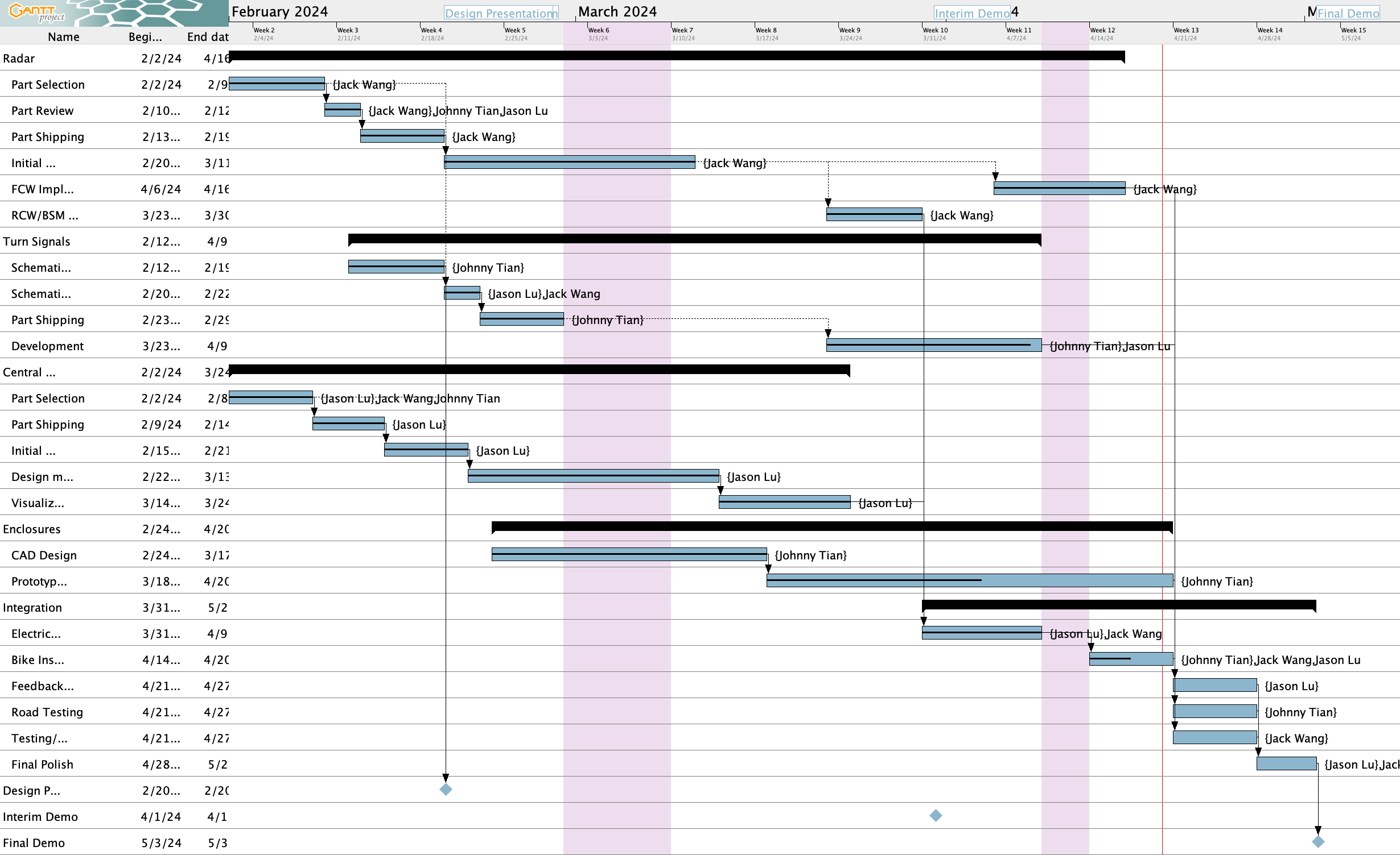
Here are the schedule updates since last week:
Completed tasks 
- FCW implementation
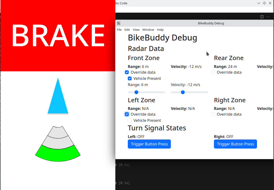
- Electrical/software integration – We have communication with all electrical components and between software
Lagging tasks 
The following tasks are behind:
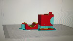
- Enclosure prototyping/refinement/final build – This task is supposed to be done by EOD 4/20, but we’re not there yet.
- We have enclosures for the radars, buttons, Pi, battery pack, and display 3D printed, but adjustments need to be made to the battery pack enclosure so the battery pack can fit, the Pi enclosure so wires can be routed, and the screen enclosure needs a cover.
- The front radar also needs a mounting system
- We also have not sealed anything for waterproofing
- The turn signal lights are mounted onto the bike along with the rear radar, but we are considering redoing the mounts to use a thicker material for better stability.
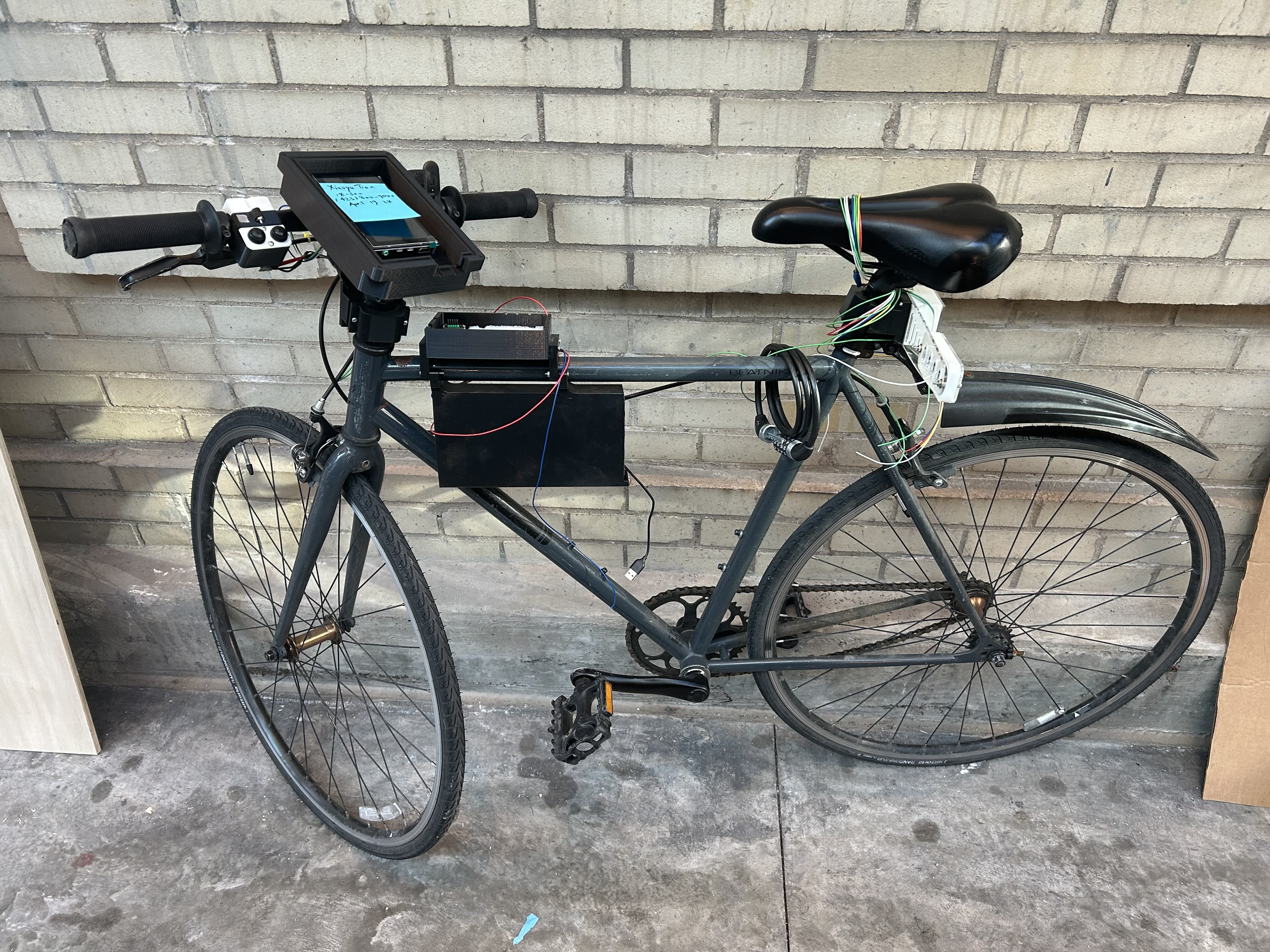
- Bike installation – This task should also be done by EOD 4/20, but we’re not there yet either. Here’s the current status (✅ = installed, ⚠️ = technically installed but not fully functional, ❌ = not installed):
- Turn signal buttons: ✅
- Turn signal LEDs: ✅* (may need to redo mount)
- Rear radar: ✅* (may need to redo mount)
- Front radar: ❌
- Raspberry Pi: ⚠️* (installed but will need to modify enclosure design)
- Battery Pack: ⚠️* (installed but will need to modify enclosure design)
- Display: ⚠️* (partially, need cover)
- Turn signal development – See Jason’s update for details in the “Adventures in magnetometer calibration” section, but this is still not completed
Miscellaneous task changes
- For the enclosure, we combined the prototyping/refinement and final build tasks into one task