Christian’s Status Report for 3/14/26

This week I made more edits to our housing design to account for the new size of our sensor PCB, and also experimented with code for integrating a pressure sensor into our design.

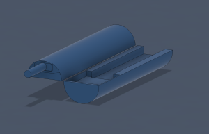
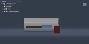
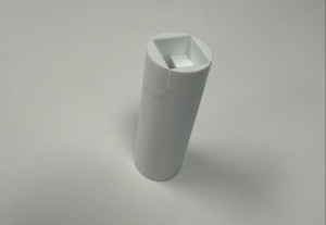
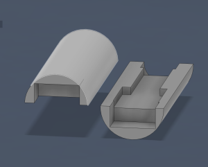
The idea behind the revised housing design is for our new sensor PCB to have a good field of view near the tip of the pen, while making the tip a lot narrower so that writing feels more natural.  This thinned out tip design is possible because our new optical sensor is a lot more compact that our initial one. This thinner tip also allows for our sensor to fully utilize its range of angle in the position it’s on our PCB.

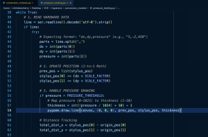
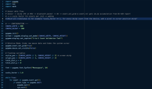
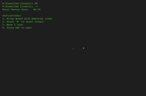
I also worked a bit with code that replaces a button click for drawing with a pressure sensor threshold. As mentioned in our team report, we’re aiming to replace some of our button functionality with a pressure sensor, which will eliminate the need for a user to repeatedly press a button to draw versus move.

As mentioned before, progress is just a bit behind because of the waiting period for our sensor, but now that our PCB is getting in next week, I can expedite with lots of testing and tuning next week.

By next week, I will start integrating actual data from our MCU and sensor, since our physical PCB should be getting in by next week.

Team Status Report for 3/14/26

At the moment the most significant risk for our project is correctly integrating all of the parts into our 3D pen case and making sure we mount the optical flow sensor correctly onto the tip of the pen. If any of this is implemented or positioned incorrectly we could lose out on a lot of accuracy with our surface tracking. These risks are being managed by constantly going through different pen case iterations to see which one works the best for our design and overall just doing a lot of testing of the individual components and the components altogether in order to perfect our tuning of the design. The contingency plan we have is plenty of backup components like MCUs and optical flow sensors just in case something breaks and we also left a good amount of time for testing just in case we need to make small design pivots.

The only design changes we’re considering is replacing our initial button integration with a pressure sensor. This allows us to eliminate the need for a user to continually press a button to change between move and draw modes, but rather use pressure thresholds, which feels closer to natural writing. Our schedule remains the same.

Here are some progress pics:


Tsairus’s Status Reports for 3/14/26

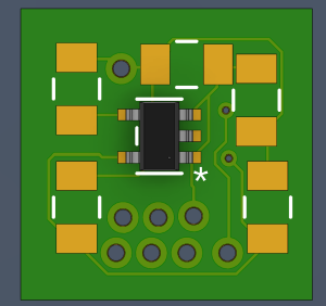
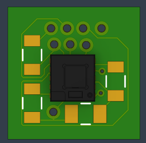
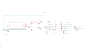
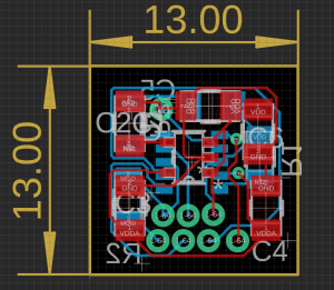
This week I spent time creating the PCB schematics and layout for the optical flow sensor that will help track the pen’s linear movement across any surface. I also spent time looking for the other components that would go on the PCB to support the optical flow sensor like voltage regulators, capacitors, and resistors and put in an order for those. Here are a few images of the schematic, layout, and 3D rendering of what the top and bottom of the PCB will look like:

Top

Bottom

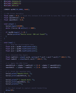
I also spent some time experimenting more with the built in IMU on the XIAO MCU board to test out how we plan on measuring the rotation and orientation of the pen to allow the user to hold the pen in a comfortable way. Here is that test code so far:

My progress is on schedule since I was able to successfully create the PCB and work on some of the IMU implementation. Next week I hope to solder the PCB together and do some physical testing to make sure everything works properly. The PCB should arrive on Monday or Tuesday so I should be able to start soldering it together one of those days.

Christian’s Status Report for 3/7/26

This week I worked more on iterating the 3D housing, as well as planning out testing for when we receive our sensor.

For the 3D housing, I allocated ~1mm of extra space for each component to account for manufacturing differences, and I rearranged the parts so that our MCU can be closer to the tip where users will likely hold the pen, so that our IMU can be more accurate. I also separated out the portion of the housing for the tip so that I can slim out the rest of the body, which will allow for a more comfortable writing experience. I also had to adjust the tip dimensions to account for our new optical sensor.

I haven’t made much progress with the conversion module since I already have the software side of it down as much as I can without having the sensor. Going further with tuning the conversion module has been bottlenecked by our troubles with getting a sensor, so when we actually do have it physically and integrated with our PCB, I can continue in tuning and testing the conversion module for the latency and CPI setting of our physical part. My progress is a bit behind because of this, but since we have our MCU’s in-hand now, I plan to send some “fake” CPI data from the MCU to try and better prime the conversion module for the real data when we get our sensor physically. This, in addition to cutting down in weight on our 3D housing by trimming excess plastic, is what I plan to get done in the next week.

Team Status Report for 3/7/26

Previously our most significant risk was actually getting the motion sensor but after working with the vendor we finally received the sensor and datasheet that we wanted and now need to make a PCB for it. So we think now the biggest risk is just receiving the PCB on time before our interim demo and making sure we have the 3D printed casing ready for all of our parts. The PCB will be completed by this weekend so it can be sent of Monday which ideally should be enough time to receive it before the demo and the 3D case has been going through multiple iterations as well to ensure all the components fit. The main contingency plan we have is if the PCB does not arrive in time we do have another backup motion sensor that we took from a mouse that is a through hole component so we could temporally wire it up to a breadboard or something just to show our design working until we receive the PCB.

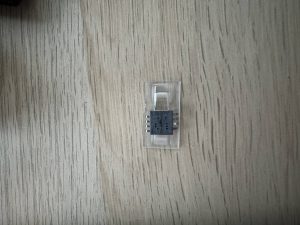
There has been one change to our design which is the type of optical flow sensor. We have managed to receive an optical flow sensor with a different part number and is much smaller than the previous one we were considering. This change was necessary since the other optical flow sensors we hard to find and this was the one the vendor recommended to us. In addition, the other optical flow sensors are much bigger so with this new one would allow our pen tip to be smaller. We think the only cost we incur from this change is we will most likely need to change our pen tip size to fit the new motion sensor other than that everything else pretty much remains the same. We will just continue to experiment with the 3D pen case to mitigate this.

Here is our updated schedule: 18-500 Gantt chart – Gantt Chart

Week-Specific Items

A was written by T’sairus Beasley, B was written by Christian Cherry, and C was written by Jamari Toussaint.

Part A (Global Factors):  To address global factors, our digital pen is designed to break down the geographic and socioeconomic barriers associated with digital education and creative work. In many regions and non-academic environments, users lack access to expensive hardware like tablets or specialized displays. By utilizing an optical flow sensor and IMU inside of a pen to track movement on any standard surface like a basic wooden desk our product allows anyone with a basic, low-cost Bluetooth-enabled laptop to have access to high-quality digital tool. Furthermore, the pen’s architecture directly accommodates users who are not technologically savvy since the onboard MCU handles all the complex coordinate transformation math locally and the pen acts as an universal Bluetooth device. This means users around the world are not required to download specialized drivers, navigate complex software installations, or pay for subscription ecosystems. Our device makes digital literacy and tools globally accessible.

Part B (Cultural Factors): The transition from physical to digital mediums can often disrupt traditional methods of writing and artistic expression. To address these cultural factors, our stylus respects these by very closely mimicking the physical form factor, weight, and tactile experience of a traditional pen. In addition to this, by calculating orientation with the IMU and MCU locally and transmitting these results to the digital canvas, our stylus preserves the user’s natural handwriting style and stroke dynamics. This ensures that users are not forced to adapt their cultural writing behaviors to suit rigid technology. Instead our stylus technology seamlessly adapts to the physical habits of the user and allows their experience to feel more natural and align with the norm.

Part C (Environmental Factors): To address environmental factors, our design mitigates the issues typically associated with traditional writing. Traditional writing consumes tons of paper and contributes to negative environmental impacts such as deforestation. Our pen design eliminates the need for paper entirely and allows users to digitize their work by writing directly on any desk or table surface which are inherently reusable surfaces. Also the pen implementation reduces electronic waste by integrating a rechargeable LiPo battery and utilizing lead-free solder on the custom PCB. This helps the pen avoid the toxic metal waste generated by disposable alkaline batteries. Finally, the modular design of the pen case allow users to open the casing and replace individual components rather than discarding the entire pen if a single part fails.

Tsairus’s Status Reports for 3/7/26

This week I spent time working on fleshing out the optical subsystem and power subsystem for the design report.  I also spent some time analyzing the tradeoffs between our design choices and portraying those in tables to help better show how our design came about. For the optical subsystem,  I spent time deriving the equations for how we calculated the CPI that will be used by our pen and I finalized which optical flow sensor we will be using for our design. Here is the CPI calculation for our pen:

For the power subsystem, I spent time deriving the equations for what our power system will look like and why we chose the battery we are going with. Here is the calculations for that:

One last thing I did this week outside of the design report stuff is I spent time working with the vender of the optical flow sensor to receive the proper optical flow sensor and datasheet that we want to use for our pen. The optical flow sensor has been received and now the biggest thing to work on is the PCB for it.

My progress is a little behind because I was hoping to have the PCB done and sent off before spring break but I was waiting for the vendor to approve of me receiving the datasheet and the sensor. This minor setback should be okay since I plan on finishing the PCB today and tomorrow so it can be sent off to the fab on Monday. So my main deliverables for this week is to finish the optical flow sensor PCB this weekend and spend next week setting up our microcontroller and working on the IMU implementation for the orientation of the pen while we wait to receive the PCB.

Christian’s Status Report for 2/21/26

This week I was able to get the first physical 3D print for our stylus housing and start on the next iteration, as well as update our conversion module plan.

Our current stylus housing is a bit short, but the thickness of it sits comfortably in the hand. Even though we don’t have our MCU yet, I personally have a different MCU model from the same company that has the same dimensions, so I was able to test the fit of the housing with that. Within this next week, in addition to making the stylus longer, I am splitting the body in two to make it easier to insert and remove parts. I will also rearrange the positioning of the parts some to account for our IMU needing to be tested in variable positions to get the most accurate reading in relation to hand motion.

In terms of the conversion module, I came upon a really great Python library called pygame that natively works with the OS to use pixels as its measurement distance and directly grabs dx/dy data from the Bluetooth device buffer before it’s optimized by the OS. This simplifies the work needed to be done for our conversion module, and allows me to focus more on helping make sure our MCU and sensor outputs the optimal CPI for our application so that our users have a smooth drawing experience. I used Gemini to help with making a test program that measures x and y differences of CPI and pixel counts using the pygame library.

Progress is going well, I just need to send in the next iteration of our 3D print this weekend.


Jamari’s Status Report for 2/21/26

This week I was able to find and create a basic software program for tracking standard mouse inputs to performing drawing functions. The code utilizes event handlers that’s synced with the mouse through html. I also created some javascript code for scanning and connecting a bluetooth device. It currently needs testing as we are waiting for our microcontroller to come in can test the BLE connection of the code + sending basic data. I have also been working with Christian as we may consider a different canvasing approach through pygame, which has built-in functions for better processing bluetooth input.

This week I plan to look more into the structure our of bluetooth communcication. I’ve followed some steps for getting the testing environment onto my device. Now we need to work on setting the struct for what data to send using the GATT protocol.

Team Status Report for 2/21/26

The most significant risk that could jeopardize the success of the project is still the motion sensor since we have still been struggling to find one that would work for our intended purpose. However, this risk has been managed since we were able to find an old mouse lying around and break that apart to take the motion sensor from it. So we will spend time testing that to make sure it works for our intended purpose. If not our only backup so far is to try to get the IMU to effectively track linear motion which has not provided the best results so far since it does not work very well on small movements. Further testing of this will be done just in case.

The only thing that’s changed with our design this week is that instead of building a conversion module from the ground up, we found a Python library called pygame that interfaces with our computer OS to do 1-to-1 CPI-pixel mapping. We will be using this library for the base of our stylus data interfacing after BLE communication. We also may need to change our design depending on which motion sensor we end up choosing. The reason for this is the one we originally wanted is too hard to find and we are still testing the current one we found.  The good thing is all of the motion sensors work relatively the same with slightly different resolutions so the cost for switching is lower resolution but that should not be too much of a problem since we were planning on working on the lowest resolution anyway to start. Overall we can still make it work with mostly any mouse motion sensor we find.

Here is the updated schedule: 18-500 Gantt chart – Gantt Chart

Tsairus’s Status Reports for 2/21/26

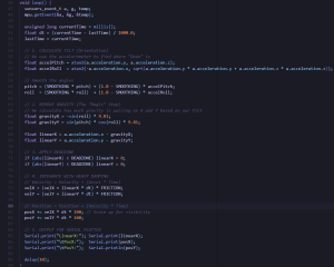
This week I spent more time testing the IMU implementation to see how well the IMU will work in our product. I also tried testing again how well the IMU could detect linear movement and implemented the code in a slightly different way since before I was trying to track the IMU on the surface but then realized the IMU would actually be in the air inside the pen shaft which changes the implementation. The IMU work slightly better when in the air but still does not work the best on small movements. Additional testing and algorithms will need to be done. Here is the main body of the code for that:

My progress did fall behind a little since I was still struggling to find the mouse sensor and I did not want to start the PCB until I knew the exact part we will use. However, Christian did manage to find an old mouse lying around and I was able to spend some time this week breaking it open and unsolder the mouse sensor from it.

My plans for next week is to test this mouse sensor to see how well it is able to track the surface and send that data to the computer. Also some time at the end of next week I should be able to receive a datasheet from the vender in addition to a quote to buy the sensor if it fits our needs and start working on the PCB schematic/layout. So deliverables is to test the mouse sensor and hopefully finalize the motion sensor we want to use.