
This week I spent most of the time testing the integration of the IMU and optical flow sensor with the MCU to make sure we were meeting our use case requirements. Most of the testing of those components are done and the main thing that needs to be completed now is tuning the sensitivity of the optical flow sensor and integrating the fsr with everything else. My progress is on schedule and my deliverable for next week is to finish the fsr stuff and finally finishing integrating everything inside the pen.
Tsairus’s Status Reports for 4/18/26
This week I managed to finish assembling the PCB together and doing all the necessary physical testing to make sure the PCB works. I also soldered the wires that we will use to the PCB to make it easier to connect everything to the MCU. When testing the PCB all of the voltages and connections were correct. Here are some pictures of the PCB:
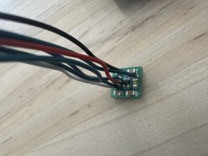
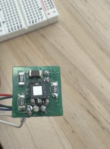
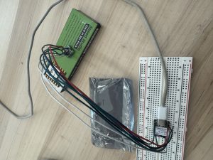
In addition to this, I also wrote some code to test the PCB and MCU integrated together and I was able to successfully get the SPI communication working and the MCU was able to receive the x and y data from the optical flow sensor. One last thing I did was write some test Bluetooth code to see if the PCB and MCU could work together to move my computer mouse by communicating through Bluetooth and this test was successfully as well.
I am currently on schedule and the deliverables I hope to complete next week is integrate the force sensitive resistor with the PCB and MCU to make sure the pressure sensing works and do any last firmware clean up to maximize performance of our system. After that all that is left is just testing.
Week Specific Items
Some knowledge I found necessary to learn in order to accomplishes the task of the project was how IMUs and optical flow sensors worked because without this knowledge I would not have been able to effectively write firmware that could use these components. I also needed to learn more about sensor fusion since our project will be receiving data from different components like an IMU, optical flow sensor, and force sensitive resistor so understanding how to fuse all this data together was important for functionality. In addition to this, I needed to remind myself of good PCB habits since our project needed a very small scale custom PCB and there was not much room for error due to the time constraint. The learning strategies I used to obtain this knowledge is watching a lot of youtube videos and reading a ton of documentation and datasheets. I also used AI from time to time to explain concepts that I was unsure about like how optical flow sensors worked or what does connection interval on Bluetooth mean.
Tsairus’s Status Reports for 4/4/26
This week I managed to work on the PCB design fixes and submit a new order request for the new updated PCB. Here is the new PCB:
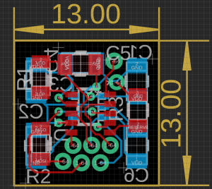
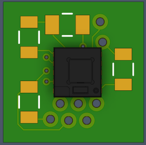
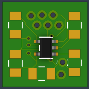
My progress is on schedule and next week I hope to have received the new PCB and solder all of the components onto it. I also want to finish the physical testing of the PCB so that I can focus more on integrating it with the other components.
Week Specific Item
My primary responsibilities are the optical flow PCB, the IMU functionality, and the microcontroller data pipeline. Here are the tests I am thinking about using for verification:
For the optical flow PCB I plan on first doing some physical testing like making sure none of the traces are shorted and all the connections are correct. Then I will run some communication test to ensure the SPI communication is working so I will read the hardcoded product ID of the sensor and make sure the microcontroller receives it correctly. Finally I will run some accuracy test where I will move the PCB 1 inch on a surface and try this with different CPI settings (400, 800, 1200, etc.) and make sure that the sensor outputs the correct number of counts per inch. For example, at 400 CPI when I move the sensor in the x-direction 1 inch the deltaX value should equal around 400.
For the IMU functionality, one test that I already ran is testing how accurate the IMU tilt is so tilting the IMU 0, 30, 45, and 90 degrees and checking what the IMU output was. The IMU tilt was usually within ~3-5 degrees of the tested angle. Another test I was thinking about running was testing how much the IMU drifts using the current smoothing filter we have so if I leave the IMU stationary on a surface for a few minutes I can record how much the IMU angle fluctuates.
For the microcontroller data pipeline, one test I was planning on doing was inputting hardcoded dummy data and eventually real data into the microcontroller and test how well the dynamic CPI function works. For example at a 60 degree tilt and baseline target CPI of 400 the math should be 400/cos(60) which is a new target CPI of 800 so from that I will verify that the microcontroller correctly sends the correct CPI value to the optical flow sensor. I will also run some latency test to make sure all if this processing happens under the time constraint.
Tsairus’s Status Reports for 3/28/26
This week I managed to receive the PCB and the components that go with the PCB. After testing, I realized that one of the footprints on the PCB was flipped so the optical flow sensor cannot be solder there else it will destroy the chip. So I will need to most likely reorder the PCB for the final demo and finish the physical testing. Here is the PCB:
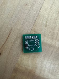
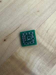
I also worked on the code for the integration between the IMU, optical flow sensor, and the MCU so that when the PCB is fully done everything can be easily integrated and tested.
My schedule is behind since I have to reorder the PCB. The actions I will take to catch up is finish fixing the PCB this weekend then reorder it on Monday so that towards the end of the week I can solder it and test it again. Next week I hope to have the PCB fixes done and hopefully have the new PCB received and ready for further testing.
Tsairus’s Status Reports for 3/21/26
This week I managed to further test the IMU rotation and tilt for the pen to ensure that it is properly calibrated for the user to comfortably hold the pen. I also spent time thinking through some of the math for how to convert the titled version of the X and Y data from the optical flow sensor into a non-tilted version so that we can properly pass this data to the computer without any discrepancies. Here is the math for that:
Compensated dX = Sensor output dX / Cos(θ)
Compensated dY = Sensor output dY / Cos(Ψ)
My progress is still on track since the PCB and its components should arrive this Monday or Tuesday and I can spend time this week soldering the PCB together. My deliverables for next week is to solder the optical flow sensor PCB together, do some physical testing of the PCB to make sure it is functional, and look more into dynamic CPI adjustment based on how the user tilts the pen to ensure maximum accuracy.
Tsairus’s Status Reports for 3/14/26
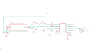
This week I spent time creating the PCB schematics and layout for the optical flow sensor that will help track the pen’s linear movement across any surface. I also spent time looking for the other components that would go on the PCB to support the optical flow sensor like voltage regulators, capacitors, and resistors and put in an order for those. Here are a few images of the schematic, layout, and 3D rendering of what the top and bottom of the PCB will look like:
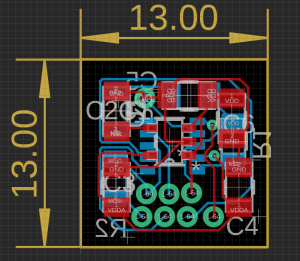
Top
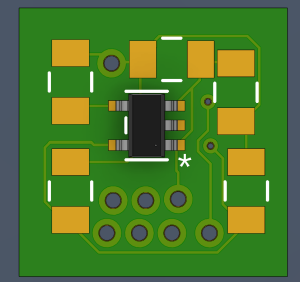
Bottom
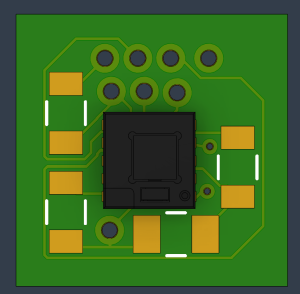
I also spent some time experimenting more with the built in IMU on the XIAO MCU board to test out how we plan on measuring the rotation and orientation of the pen to allow the user to hold the pen in a comfortable way. Here is that test code so far:
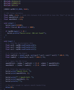
My progress is on schedule since I was able to successfully create the PCB and work on some of the IMU implementation. Next week I hope to solder the PCB together and do some physical testing to make sure everything works properly. The PCB should arrive on Monday or Tuesday so I should be able to start soldering it together one of those days.
Tsairus’s Status Reports for 3/7/26
This week I spent time working on fleshing out the optical subsystem and power subsystem for the design report. I also spent some time analyzing the tradeoffs between our design choices and portraying those in tables to help better show how our design came about. For the optical subsystem, I spent time deriving the equations for how we calculated the CPI that will be used by our pen and I finalized which optical flow sensor we will be using for our design. Here is the CPI calculation for our pen:

For the power subsystem, I spent time deriving the equations for what our power system will look like and why we chose the battery we are going with. Here is the calculations for that:

One last thing I did this week outside of the design report stuff is I spent time working with the vender of the optical flow sensor to receive the proper optical flow sensor and datasheet that we want to use for our pen. The optical flow sensor has been received and now the biggest thing to work on is the PCB for it.
My progress is a little behind because I was hoping to have the PCB done and sent off before spring break but I was waiting for the vendor to approve of me receiving the datasheet and the sensor. This minor setback should be okay since I plan on finishing the PCB today and tomorrow so it can be sent off to the fab on Monday. So my main deliverables for this week is to finish the optical flow sensor PCB this weekend and spend next week setting up our microcontroller and working on the IMU implementation for the orientation of the pen while we wait to receive the PCB.
Tsairus’s Status Reports for 2/21/26
This week I spent more time testing the IMU implementation to see how well the IMU will work in our product. I also tried testing again how well the IMU could detect linear movement and implemented the code in a slightly different way since before I was trying to track the IMU on the surface but then realized the IMU would actually be in the air inside the pen shaft which changes the implementation. The IMU work slightly better when in the air but still does not work the best on small movements. Additional testing and algorithms will need to be done. Here is the main body of the code for that:
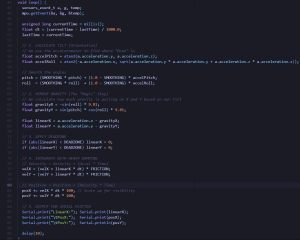
My progress did fall behind a little since I was still struggling to find the mouse sensor and I did not want to start the PCB until I knew the exact part we will use. However, Christian did manage to find an old mouse lying around and I was able to spend some time this week breaking it open and unsolder the mouse sensor from it.
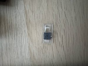
My plans for next week is to test this mouse sensor to see how well it is able to track the surface and send that data to the computer. Also some time at the end of next week I should be able to receive a datasheet from the vender in addition to a quote to buy the sensor if it fits our needs and start working on the PCB schematic/layout. So deliverables is to test the mouse sensor and hopefully finalize the motion sensor we want to use.
Tsairus’s Status Reports for 2/14/26
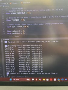
This week I decided to look into the PCB Schematic and look more into the motion sensor trying to find vendors that sell them. Originally I wanted to have the PCB schematic and layout done but I first need to find a vendor for the motion sensor we want before I can finish doing this. I am currently speaking with a vendor to arrange a part order for a particular motion sensor. So instead of sitting around waiting for that I decided to also test the IMU functionality to see if it would be possible to implement our entire pen’s motion just with the IMU. After testing, the IMU did not work that well at detecting position as we would have hoped so we are thinking of sticking to our original design of using an optical motion sensor. Here is some photos of the IMU temporarily being setup and tested using an STM32 board until we get our XIAO MCU:
:
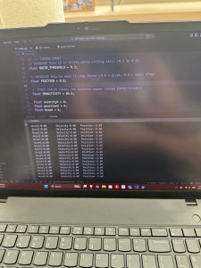
My progress is a little behind since I was hoping to have the PCB stuff done and ready to order by the end of this week. The actions I plan on taking to catch up is continue talking to the vendor I am hoping to buy from and get the datasheet from them so that way I can start building the schematic and laying everything out by the next status report. By next week, I hope to finally have the motion sensor decided and ready to order. In addition, I am hoping to have the PCB schematic and layout for the motion sensor completed as well.
Tsairus’s Status Report for 2/7/26
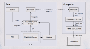
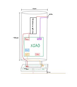
This week I managed to come up with a diagram to properly show how all of the components in our product comes together and draw out a visual representation of what I think the pen should look like. I also took the time to take measurements of the components to help figure out the dimensions that the pen should be and looked into the specs of the motion sensor to make sure it could accomplish the tasks we need from it. In addition to this I spent time coming up with technical challenges and some risk mitigation strategies to counteract what we think our technical challenges are. I think my progress is on schedule since I was able to come up with a reasonable hardware design and pretty much finished looking for the parts we want.
For next week I am hoping to complete the first round of the PCB schematic and layout for the motion sensor so we can send that to the fab and test it soon to make sure there are no errors.