Yuyi Shen’s Status Update for April 18 2020

This week, I mostly assisted Joy and Kenny with the integration of the mount electronics with the remainder of the mount. In Kenny’s case, this was just a matter of checking in on his progress with assembling the electronics (both on PCB and breadboard). In Joy’s case, this meant going over the meaning of the logic inputs of the unipolar and bipolar motor drivers, and the sequences in which they were supposed to be driven to effect a full-step sequence.

I also checked Joy’s motor driver code against the full-step sequences described online for bipolar and unipolar stepper motors, and wrote test cases in motor_driver/main.cpp. If all goes smoothly, main.cpp should cause one of the unipolar Digikey motors to rotate 3 times before reversing to the original position at 1 RPM, while setting one of the bipolar NEMA 17 motors to rotate at 60 RPM for a minute before turning off.

As a debugging aid, I also drew logic diagrams for the bipolar motor driver inputs that indicate the direction of current flow for different values of EN and PWM and labeled full-step sequence diagrams:

I felt that it was unnecessary to do the same for the unipolar motor driver, due to the lower complexity of the stepping sequence.

Thus far, I’m on track relative to the schedule. Next week, I need to start working on preparing materials for the demo video that cover my contribution to the project, while continuing to advise Kenny on the assembly and testing of the motor drivers. Since the vast majority of my tasks are complete, I will also spend some time working on the final report for the project.

Joy’s Status Update for 2020-04-18

This week I finished up the code for controlling the unipolar and bipolar stepper motors. It consists of two classes, one for controlling unipolar stepper motors and one for controlling bipolar stepper motors. The code I wrote uses std::thread to set the relevant GPIO pins in a loop so that multiple motors can be controlled at once. It also implements step-counting for tracking the number of revolutions taken. The GPIO library used was WiringPi. I found this article very helpful.

Next week, I will be working on checking that the CV code can run on the Pi, allowing the CV to use camera input, and hooking it up to motor control. I will also be working with Kenny to modify his polar alignment code from earlier in the semester to work with the rest of the system.

Joy’s Status Update for 2020-04-11

My tasks for the week:

  • Work on interface between motor controller board and Pi
  • UI fixes (e.g. selecting an object to track from live video) (not as important)
  • Automatic calibration for the compensator motor’s speed using CV (not as important)

What I have from this week:

Two squarewaves in quadrature from the GPIO pins of the Pi, at a much lower frequency than necessary for the PWM signals for motor control. (I don’t have an oscilloscope, although I might be able to hack something together with an Arduino, if I can find one) These are for the unipolar stepper motors for the compensator and test setup.

I lost some time trying to set up the Pi, and I’m also working on porting the code from the last few weeks to the Pi.

My progress: I’m behind on the motor controller interface. I expected to have more done.

Next week: More work on the motor controller interface.

Kenny Ramos Status Report for 4.11.2020

System Changes:

The main changes done this week basically break down to design changes to accommodate parts trickling in over time. Most of this is adapting the previous eq aligning design to the new barn door tracker. After receiving the universal stepper motor couplers I should be able to assemble the top portion of the diagram above with the exception of the motors since I do not have the pcb’s yet and I would like to thoroughly test them before placing them into the mount. Some things to point out in the diagram below include:

  1. The polar scope is manually (by us, not the “user”) aligned parallel to the hinge joint adjacent to the scope.
  2. The compensator motor is attached to the declination base and the universal hub is attached to the carriage bolt.
  3. The motor is kept from spinning by two #4 threaded rods that are locked into the barn door tracker base by two #4 nuts each. As the cariage bolt actuates the motor is pulled along with it so spacing must be kept in mind and a hole of sufficient size must be bored in the declination base.
  4. The base below the main barn door tracker compensator is essentially the same design as the one previously done by Joy for the previous iteration of this project. Some adaptations have been made to fit the new requirements. (As discussed above).

Progress has also been done in adapting logging for the Arduino. Getting the logger right now outputs to csv in real-time via a python script.

Risks:

Unfortunately, the arrival of the incorrect board types set back demo-readiness a fair bit, hopefully once the new boards arrived the new design will be ready for it. So that’s a risk that we could face.

Yuyi Shen’s Status Update for April 11, 2020

This week, I helped handle a handful of shipping/ordering mishaps. The PCBs that we had originally ordered were somehow mixed up with another team’s order, and Kenny ended up receiving a networking/audio controller board instead of the unipolar motor driver I had designed. Quinn re-ordered the motor controller PCBs, and they should arrive by the 17th.

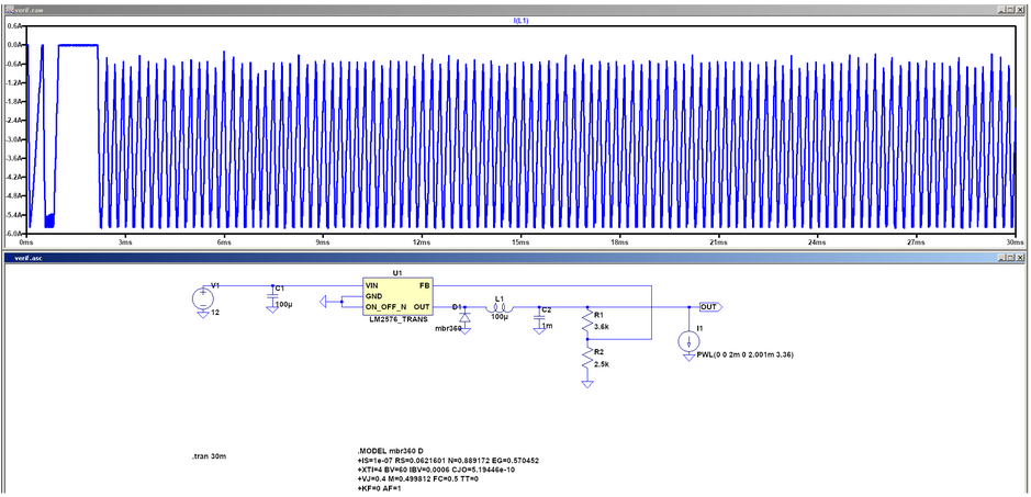
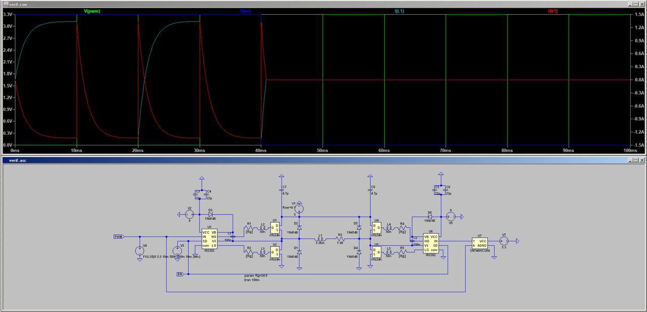
In addition to dealing with the PCB mix-up, I had to revise our Digikey order for the NEMA 17 motor driver parts after reviewing simulation data of the motor driver power supply and the motor driver itself. After extending the transient simulation time for the motor driver power supply, I found that the SMPS’s inductor current oscillated between 0.6 and 6A, with an RMS average of 3.73A:

Since this was far beyond the current rating of the original inductor I’d specified for the SMPS, I asked Joe to cancel the original Digikey order, and changed the Digikey cart to use inductors that were rated for a maximum of 9A RMS. Since this maximum current would result in the maximum survivable temperature rise for the inductor (roughly 60 degrees C assuming the ambient temperature is 25C), I estimated that the newly selected inductor would experience temperatures of roughly 50C in operation. Kenny will need to be careful not to touch the SMPS inductors with his bare hands while the NEMA 17 motors are running, but they will otherwise be 35C below their maximum operating temperature.

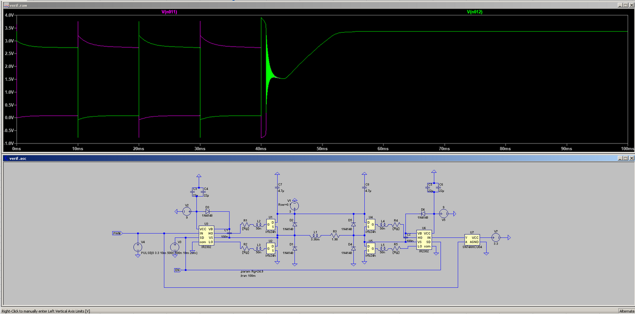
Furthermore, a review of the transient currents through the motor driver core’s bootstrap diodes in LtSpice revealed that they experience regular spikes on the order of 1.5A and an inrush current in excess of 2.5A. Since their maximum current spike rating was 2A, I judged this to be potentially hazardous and switched them out for MBR360s, which are rated for 80A spikes. We were already ordering a handful of MBF360s for the motor driver SMPSs, so this wasn’t much of a load on the budget.

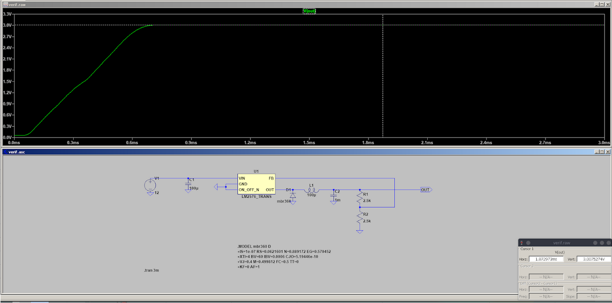
Lastly, I checked the power dissipation of the LM2576 regulator that I was planning on using for the motor driver SMPSs in simulation, and found that it would dissipate an average of 11W in steady state operation. Since the thermal resistance of the regulator’s package was specified to be 32.4 C/W, this would have resulted in a temperature rise of about 360 degrees Celsius if we ended up operating it without a heatsink. Obviously, this would have destroyed the device rather quickly. To prevent this, a heatsink with a natural thermal resistance of 3.8C/W was added to the original Digikey cart, in addition to a mounting kit with a mica insulator for the regulator tab. This thermal resistance is slightly less than half of the maximum required thermal resistance to keep the regulator at or below the maximum operating temperature of 125C (9.04 C/W), and should keep the regulator temperature down to 67C.

Lastly, I made sure to put in an order for 3 ULN2803 Darlington transistor arrays as a contingency in case the PCB re-order for the motor controller doesn’t get shipped to Kenny’s house in time for us to make the deadline for the demo.

Thus far, I am on track with my contributions to the project. Next week, I hope to consult with Kenny on the final construction of our camera mount’s electronics, and with Joy on the interface between the Raspberry Pi and the motor controllers.

Team B1 Update for 4.11.2020

Risks:

One major risk we’ve come across recently is that of a mix-up occurring during the shipping or ordering of items we order from the course staff. This week, instead of receiving the unipolar motor driver that was expected, we got an audio controller PCB from OSHPark. After a few days of inquiries, it was found that the PCB we received was in fact associated with another team’s design, and the course staff decided to re-order the board design. As a contingency for the delay caused by this particular mix-up, it was decided to order a set of darlington transistor arrays from Sparkfun to serve as a potential (if less effective) replacement for the PCB. As a contingency for future mix-ups, we intend to investigate alternatives to required components that can be physically picked up at a store by the team member responsible for assembling our project hardware.

System Updates:

Our previous design made use of an external touch enabled display to provide user interfacing with our raspi. However, in an attempt to reduce project complexity as well as to provide a contingency in the case that the raspi is not powerful enough to both compute image-based compensation on top of a GUI and touch screen feedback we will be altering the design. In our new altered design we will be emplogin a standard user-end notebook as the system for our GUI. This notebook will then communicate with the rpi via usart interfacing (alternatively via ethernet connection) and will provide the raspi with necessary user feedback and vice versa.

The above Gantt chart reflects the decision to move away from the usage of an external display to interface with users. Notably, the task labeled “User Interface Specification” has been struck through, indicating that it is no longer relevant for the project.

Yuyi Shen’s Status Update for April 4 2020

This week, I worked with Kenny to specify through-hole components suitable for driving the large NEMA-17 motors that were determined to be necessary for implementing the pan and tilt functions of our camera mount (see Team Status Report). Spinning out the PCB that was designed for this task earlier in the semester was found to be infeasible due to the risk of shipping delays impacting our ability to receive the boards from whichever manufacturer we decided to use (the boards would have needed to be manufactured overseas to keep costs low). We examined the possibility of simply ordering the motor drivers that were recommended on the motor supplier’s website (notably the Big Easy Driver on Sparkfun), but found them to be rated for far higher supply voltages than the motors were capable of handling.

First, we specified through-hole components for a 12V to 3V SMPS for powering the motors. We chose to use a LM2576T-ADJ/NOPB as the SMPS controller, and simply calculated the resistor feedback values for setting the output voltage to 3V. The inductor and capacitor values were kept to the recommended values in the datasheet. LtSpice was used to verify that the design would indeed produce the desired output voltage:

Then, I spec’d out through hole parts for implementing the actual H-bridges for controlling the motors (2 H-bridges per motor). IRFZ24N transistors and IR2302 gate drivers were selected, along with 24.9 Ohm gate resistors so that the driver circuit can tolerate up to 50 nH of parasitic inductance at the MOSFET gates (to reflect the implementation of the circuit on a breadboard). The gate drivers have built-in PWM and ENABLE inputs, so no additional logic was required past a single inverter for buffering the input of the 2nd gate driver. Because the gate driver ICs are synchronous, no special measures were required for generating dead time. High speed 1N4148 diodes were chosen to clamp the inductor voltages to the supply rails.

Verification was carried out in LtSpice:

Note that there are no spikes in the I(V1) waveform, indicating that the gate driver ICs are successfully mitigating shoot-through in the MOSFETs. Furthermore, the current through the inductor representing the motor coil falls rapidly to 0 when the ENABLE signal goes low, meaning that this functionality works in simulation.

There are voltage spikes at the motor coil during operation, but the flyback diodes successfully keep them within 1 diode drop of the supply rails. There’s also some ringing when the ENABLE signal goes low, but it eventually dies down to a steady-state.

Thus far, I believe I am on track for the 1st demo-in-lab, and the Gantt chart schedule. The first demo will consist of a slide show with simulation results for the motor controllers, and the layout for the motor controller PCB that was designed for the smaller compensator motor. Next week, I will first need to compile the slide show for the demo. Then, I will need to compile a Digikey cart for the final through hole components, and work with Kenny to ensure that we aren’t missing any mechanical components for the test-setup for our mount.

Team Status Update for April 4 2020

Risks:

With regards to the integration of the project components, the principal risk consists of coronavirus-induced shipping delays that could keep us from obtaining missing components on short notice. This is primarily being mitigated by having frequent discussions with one another (and especially Kenny) about parts that are missing or still in-transit.

Last week, we wrote about the increased distance between team members causing significant communication delays. This was addressed by first re-examining our regular meeting schedule, and updating it to reflect our present availabilities. Secondly, we set up a Google Form at https://forms.gle/HW3D9axC5a3YqB7x8 to serve as a rudimentary ticket system for team issues. Tickets are directed to a Google Spreadsheet within our Google Drive directory for later approval.

Changes to system:

This week, Kenny determined that the NEMA-17 400 step motors that we ordered earlier this semester are necessary to implement the panning and tilting functionality of our camera mount. This precludes the possibility of using the smaller 4096-step motors + pcbs that we ordered earlier. Because of the long shipping times associated with the cheaper manufacturers that we’d have to use to spin out the large PCBs that were designed earlier this semester for driving the NEMA-17 motors, we decided to have Kenny implement rudimentary H-bridges on a breadboard using through-hole components. Due to the timing with which orders are placed in this class, this change does not impact our schedule. Indeed, the new through-hole design has already been validated in SPICE simulation, and simply needs to be converted to a Digikey cart for ordering. The risks of implementing H-bridges on breadboard will be mitigated by using separate breadboards for each motor driver to avoid crosstalk, and a relatively large gate resistor was specified for the H-bridge MOSFETs to damp up to 50 nH of parasitic inductance at the FET gates (the circuit node that’s most sensitive to parasitic inductance). Note that this 50 nH corresponds to roughly 5 cm of wire (going by the classic approximation of 1 nH/mm for bond wires).

Changes to schedule:

The “assemble mount” task has been extended to Week 13 to allow for the arrival of the final mount components, while the laser array board layout task has been struck through to reflect our decision to have Kenny simply solder together through-hole components to implement the test setup’s laser drivers. Lastly, the User Interface board layout task has been revised to omit mentions of PCB layout, since the rudimentary UI can be implemented with switches on one of Kenny’s breadboards.

Joy’s Status Update for 2020-04-04

I hooked up the demo to the CV tracking and prototype panning and tilting by allowing output from the tracking algorithm to move the camera in the OpenGL model. The two virtual motors are controlled with a PID control loop. Code has been pushed to the s18-18400-b1-asterism repo.

Things I am behind on that I will catch up on next week:

  • Porting existing code to Raspbian
  • Figuring out how to communicate to the motor controller

Other things I will work on next week:

  • UI fixes (e.g. selecting an object to track from live video)
  • Automatic calibration for the compensator motor’s speed using CV

Update for 03/28/20

This week I worked on the tangent error calculations as well as the parametric equations for modeling the 3d piece used for hardware error correction.


Our new method of barn door tracker has inherent errors due to the way the upper arm is actuated (as the hypotenuse of a right triangle). This means that while the expected rotation rate should be constant the actual rotation that comes from this method is proportional to (dL/dt)where L is the rate of height change for the threaded rod.


This means that error from desire rate depends on arm length, thread pitch, and rate of thread rotation:


E(t) = (Sidereal Rate) * t – 2 * arcsin(k * t/60s * (thread_pitch) / (2 * arm_length))


Where k is rod rotation rate per minute.

Assuming a 200mm arm, a thread pitch of 1.27mm per rotation, and a sidereal rate of 2pi/86164s we get the following error:


E(t) = 2pi/86164s * t – 2 * arcsin(k * t/60s * (1.27)/(400mm))


Letting t E [0s, 10770.5s] (Or 1/8th of a sidereal day and ~ 3 hours) we get the following graphs for different rates k:

This provides the linear displacement perpendicular from the camera arm.


There are two methods for compensating for this: a software method and a 3d printed error compensator method.


The software method involves approximating the theta value necessary and working backwards to derive the necessary linear thread displacement. This can be easily implemented on the side along with the other motor drivers and could prove to have a smaller latency than the hardware method.


The hardware method for tangent error compensation involves using a constant rate for the thread motor and printing out a curve whose altitude is the negative of the error shown in the graphs above. In turn effectively reducing the error to 0. The only additional modeling requirement for this method is to find the parametric equation for parallel displacement which for pi/4 radians is L*(1 – cos(theta)) over [0, pi/4] radians and time of [0, 10770.5]s as before. Due to the fact that this is a piece that is on the bottom of the actuating arm we require that the error is negative throughout so we would go for constant k E [0.8, 1.6].


The advantages for using this method over the software method is that once the piece is printed the sidereal compensating motor only needs to be run at a constant rate and all of the error compensation is contained within the 3d printed piece.


Further updates:

  • I set up Arduino ADC logger that works through the Arduino IDE’s serial communicator.
  • Most items that were shipped before spring break have arrived to my house so the only things that are left are our orders from last Friday that include motor/laser led controllers/drivers and further structural pieces.
  • This week I will be setting up for measuring some of the demos possible as well as discussing our options for tangent error compensation.