Joy’s Status Update for 2020-04-25

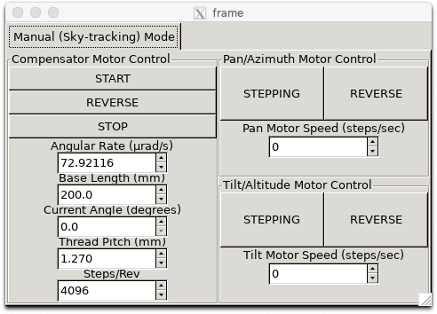
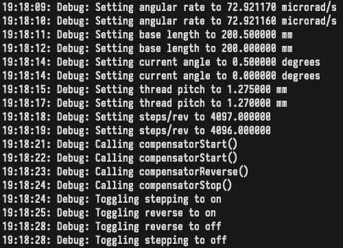
I was able to verify that CV code compiles on the Pi and works with the motor controllers and libgphoto2 camera input. I wrote a GUI app (attached is a screenshot) for the motor controllers and fixed some bugs that my teammates pointed out to me. I haven’t integrated the CV code into the GUI app yet, so I am behind on that. Next week we have our final presentation, and the week after that we have the final demo, so I will spend next week working on those with my teammates, working on integrating the CV code into the GUI, and working on any last-minute software improvements.

Joy’s Status Update for 2020-04-18

This week I finished up the code for controlling the unipolar and bipolar stepper motors. It consists of two classes, one for controlling unipolar stepper motors and one for controlling bipolar stepper motors. The code I wrote uses std::thread to set the relevant GPIO pins in a loop so that multiple motors can be controlled at once. It also implements step-counting for tracking the number of revolutions taken. The GPIO library used was WiringPi. I found this article very helpful.

Next week, I will be working on checking that the CV code can run on the Pi, allowing the CV to use camera input, and hooking it up to motor control. I will also be working with Kenny to modify his polar alignment code from earlier in the semester to work with the rest of the system.

Joy’s Status Update for 2020-04-11

My tasks for the week:

  • Work on interface between motor controller board and Pi
  • UI fixes (e.g. selecting an object to track from live video) (not as important)
  • Automatic calibration for the compensator motor’s speed using CV (not as important)

What I have from this week:

Two squarewaves in quadrature from the GPIO pins of the Pi, at a much lower frequency than necessary for the PWM signals for motor control. (I don’t have an oscilloscope, although I might be able to hack something together with an Arduino, if I can find one) These are for the unipolar stepper motors for the compensator and test setup.

I lost some time trying to set up the Pi, and I’m also working on porting the code from the last few weeks to the Pi.

My progress: I’m behind on the motor controller interface. I expected to have more done.

Next week: More work on the motor controller interface.

Joy’s Status Update for 2020-04-04

I hooked up the demo to the CV tracking and prototype panning and tilting by allowing output from the tracking algorithm to move the camera in the OpenGL model. The two virtual motors are controlled with a PID control loop. Code has been pushed to the s18-18400-b1-asterism repo.

Things I am behind on that I will catch up on next week:

  • Porting existing code to Raspbian
  • Figuring out how to communicate to the motor controller

Other things I will work on next week:

  • UI fixes (e.g. selecting an object to track from live video)
  • Automatic calibration for the compensator motor’s speed using CV

Joy’s Status Update for 2020-03-28

This week I have a demo for a mock sky, rendered with OpenGL:

I plan to hook up the demo to the CV tracking and prototype panning and tilting by allowing output from the tracking algorithm to move the camera in the OpenGL model. It was tricky getting OpenGL to work at first, so I spent some time getting the dependencies installed etc. Code has been pushed to the s18-18400-b1-asterism repo. I have yet to make sure it can compile on Raspbian, so I will be setting up a VM for that purpose later this week.

I expected to have more done by the end of this week, so I would say I am somewhat behind in terms of deliverables. I have a more concrete plan of action than I did at the end of last week though, and I consider that progress.

Plans for next week:

  • Tomorrow:
    • More points, randomly sampled from a hemisphere
    • Points that rotate around the origin independently (“objects” to track)
    • Modify mock sky and tracker so they can be hooked up together
    • https://docs.opencv.org/2.4/modules/core/doc/opengl_interop.html
  • Monday-Tuesday:
    • Modify tracker to calculate pixel distances(?)
    • Translate pixel distances into camera rotation (panning and tilting)
    • Modify the mock sky scene to allow the camera to move based on inputs
    • Calibrate based on camera fov and other parameters
  • Wednesday-Friday:
    • Port existing code to Raspbian
    • Figure out how to translate those into inputs to the motor controller

Joy’s Status Update for 2020-03-21

I have spent this week rescoping our project with my teammates. Due to lack of access of TechSpark, the hinge joint and the turntable portions of the mount will need to be somewhat modified to rely less on fabricated gears and instead on parts from McMaster-Carr. This will require some redesigning. For the object-tracking software, it seems that the bottleneck will most likely be the latency of image transfer, but the object tracking may also decrease the possible framerate. I need to start working on porting the software to the Pi, either by working in a VM or by ordering a Pi and running the software on the Pi directly. I will need to start working with libgphoto2 and attempting to feed images into the object-tracking software from a camera (e.g., a smartphone) connected via libgphoto2. It’s also important that I figure out how the mount and the motors will interface with the Pi, which GPIO pins to use, etc. As for verification of the object-tracking software, I will need to experiment with generation of mock inputs for the Pi. I am behind on this. I will also need to work out how to coordinate testing of the interface between the Pi and the motor controller board given that I will not have access to both.

Joy’s Status Update for 2020-03-07

I have talked about fabrication details with my team. We submitted a few orders this week for parts. I do not have a lot to show for the object tracking code. A short video is attached. It’s just an example of tracking with KCF (Kernelized Correlation Filters) on a video of stars.

I am somewhat behind on my tasks. I intended to have gotten further with the code than I did this week. Luckily, I have next week (spring break) to catch up.

I intend to spend next week actually writing code, figuring out how small the images can be downsampled to, calculating velocities of objects, tracking multiple objects, improving the UI for selection of objects, etc. I would also like to start working on tests for the object detection and object tracking. I am nervous about how to translate object tracking velocities to panning and tilting of the actual mount.


Joy’s Status Update for 2020-02-29

I’m two weeks behind. I got sick. I spent some time working on the design report with my teammates. I have started but have nothing to show for the demo. I have not ordered parts. Same “next week tasks” as last week, for the most part:

  • I would like to catch up on ordering parts and getting information about fabrication credits.
  • I would like to start on the object tracking demo. I will be attempting to create a demo for object tracking. I will test it with video samples. Currently, I don’t know what kind of quantitative result would be considered “passing,” but the purpose of this software prototype is to figure out how small the resolution of the images can be before the performance of the object tracking decreases dramatically.
  • I would like to start working on tests for the object detection and object tracking.
  • I would like to finalize fabrication details with my group members and begin with fabrication.

Joy’s Status Update for 2020-02-22

My tasks for the week:

  • Talk to team members about the design.
  • Order parts and talk to the right people about fabrication credits for the team.
  • Figure out with Kenny how the gearing will integrate with the rest of the mount.
  • CAD the mount in more detail.
  • If time: start on object tracking demo.

What I did this week:

  • Figured out how to attach the compensator gearbox to the rest of the mount. We plan to hold the gears in place within an acrylic box with threaded rods, bearings, nuts, and spacers.
  • CAD the mount in more detail. [ todo insert image ]
  • Work out a more detailed parts list, down to screw sizes etc. [ todo screenshot the spreadsheet ]
  • Worked on design slides with team.

My progress:

  • I am somewhat behind.
  • I didn’t order parts or get information about fabrication credits for the team. This is bad because it pushes back when we can start on mechanical construction.
  • I also hoped to start on the object tracking demo. I didn’t.

Next week:

  • I would like to catch up on ordering parts and getting information about fabrication credits.
  • I would like to start on the object tracking demo. Like Kenny did this week, in Week 7, I will be installing OpenCV (locally, not on the Pi yet). I will be attempting to create a demo for object tracking. I will test it with video samples. Currently, I don’t know what kind of quantitative result would be considered “passing,” but the purpose of this software prototype is to figure out how small the resolution of the images can be before the performance of the object tracking decreases dramatically.

Joy’s Status Update for 2020-02-15

My tasks for the week:

  • Design the mount (not including gearing)
  • CAD the mount (not including gearing) in SolidWorks
  • Figure out which parts must be purchased
  • Figure out how to fabricate remaining parts

What I have from this week:

  • A very rough SolidWorks assembly of the mount
    • Fasteners, some gears, some teeth on gears omitted
    • Tentative dimensions
    • There is an upper part of the mount that includes Kenny’s compensator gearbox, which is relatively complicated and may take up a bit of space. I have not drawn it because I am not sure how it will fit in.
  • A partial list of parts to purchase
    • From McMaster-Carr
      • 2 square turntables (6031K160)
      • 1 round turntables (1544T200)
      • 4″ of aluminum U-channel (9001K124)
        • Or maybe a different size
    • Still need to figure out what screws and other fasteners we need
  • Ideas for fabrication of other parts
    • MDF panels, which can be jigsawed
    • Gears lasercut from quarter-inch-thick HDPE
      • IDeATe doesn’t allow HDPE in its laser-cutters, but TechSpark does.
      • HDPE can be tricky to cut, melting or catching fire on the wrong settings.

My progress:

  • I am mostly on schedule. I am not completely satisfied with the design, and there are some uncertainties, but next week is also allocated to improving the CAD and integrating it with Kenny’s gearing designs.
  • I am a bit behind. I still need to figure out what size aluminum U-channel, which screws and fasteners, etc. that we require for the mount. I would like to improve the CAD so that it has more detail (e.g., the holes that must be drilled into the MDF panels). I still have not asked my team members for feedback and suggestions.
  • How I will catch up: I have Sunday and Monday to figure out parts and improve the CAD.

Challenges/Requirements for the mount:

  • Holding up the weight of the photographing equipment as well as the polar aligned compensator.
  • Having enough space to accomodate the equipment and the polar aligned compensator.
  • Having the 0.5 degree accuracy when positioning.
  • Having the torque necessary to lift the equipment and compensator.

Next week:

  • Talk to team members about the design.
  • Order parts and talk to the right people about fabrication credits for the team.
  • Figure out with Kenny how the gearing will integrate with the rest of the mount.
  • CAD the mount in more detail.