Team B1 Report for 02/29/2020

Addressing some of the pressing design oriented feedback received:


Some of the feedback we received dealt with how much fidelity the star mount could simulate actual starlight. To address this we plan to discuss the target of each subsystem test. For one, the star simulating mount does not serve the purpose of simulating actual star-light but rather the movement of stars. Since the capture device is out of scope we plan to specify certain restrictions for how much contrast there should be between an object and the “background” (space) in order to allow for accurate “object identification” (tokenization really). This threshold will be tested with generated offsets of real captures taken with a typical entry level capture device (~$700 DSLR cameras [Canon T7i or Nikon D5600]) with 55mm lenses). However, since this is out of scope our stand works with the assumption that these captures meet these metrics [A badly taken capture, for example a long exposure shot of a sodium street lamp, would not meet this].

The rest of the feedback ran along the lines of too little specification in the design presentation as well as some doubts when it comes to competitive analysis. These will all be reflected in the final draft of our design review.


Risks:

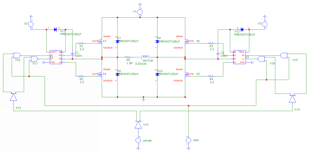
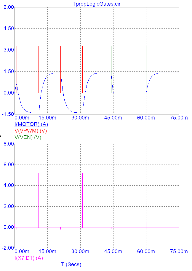
There is a risk that Yuyi won’t be able to work much on the circuitry and layout associated with the test setup this week, as CMU’s ECE Open House is scheduled from Tuesday to Thursday of this week. This could push our schedule back because this will leave Kenny to work individually on the circuit design for the laser drivers/motor drivers composing our project’s test setup. Fortunately, the impact of this is unlikely to jeopardize our project. Work on the CV and physical mount is still progressing and the test setup will not be needed until such is completed. Therefore, a contingency plan isn’t really required for this.


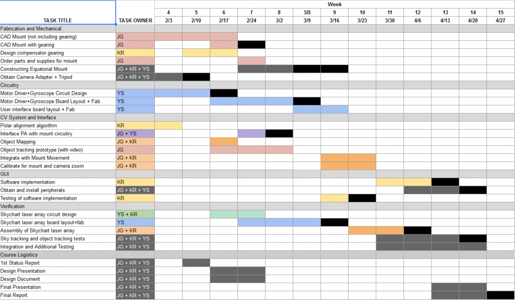
Thus far, we haven’t had a need to make changes to the system’s existing design. However, we intend to push the layout and fabrication of the user interface board of our project to the week of Spring Break. The task will then last until Week 9, when our team will begin integrating the CV with the mount’s motor system. The new Gantt chart is as follows:

Yuyi Shen’s Status Update for Feb. 29 2020

I estimate that I’m 1 week behind on the user interface board design and the layout for the motor controller board. I was also meant to start working on the test setup with Kenny, but he’s been bogged down with the mechanical portion of the project. This isn’t entirely unexpected, as I’ve been gone for almost half the week for a graduate student recruitment event. That, and course logistics have taken up a great deal of time (i.e. preparing for the design review presentation and the design report).

This week, I’ve only managed to setup my layout software with component symbols and footprints in preparation for laying out the motor driver board. Motor driver layout is precarious at best, so I’ve spent most of my time reading up on board design guidelines so that we don’t waste time re-spinning a board. I’ve also compiled a Digikey cart for the driver board: https://www.digikey.com/short/zq07q2 as a price estimate. Disregarding the cost of the PCB, the components for a single unit cost $18.91. This high price point is mainly due to the MOSFET gate drivers and H-bridge FETs, so it’s difficult to ameliorate.

To get back on track next week, I’ll first need to work with my team to get the design report done ASAP. Then, I’ll need to finalize the layout for the motor driver board and 8V power supply in the first half of next week so that we can send the orders out. In the remainder of the week, I’ll work with Kenny on the circuitry and layout for the equatorial mount’s test setup. The layout for the user interface board can be pushed back to Spring Break, since there hasn’t been much progress on the software component of the project.

Kenny Ramos. Status Report 02/29/2020

This week was particularly consumed by other logistic aspects of the class so I was unable to get some other things done. I wanted to finalize some of the simulation stuff to have more concrete numbers and figures for the design review as well as address some of the feedback we got from both our professors and peers and reflect that in our final design review.


Operational things accomplished:


  1. Finalized gearbox while I was unable to get the physical parts printed out this week I should be able to address this on the upcoming Monday class.
  2. Finalized turntable design for “star simulator” mount should be able to decide on final design by next week and get that into fabrication.


For next week the final steps to fabrication should be taken after the design review is finalized. Since our budget will also be finalized by then we hope to order every part necessary by next week as well which will allow us to start assembling after the break.

Another pressing matter is spinning up our software component development. Thankfully most of the setup work was already done in week 6 so we are able to get that done relatively quickly. After week 8 and into week 9 we should be starting on some CV prototypes for our stand, including functional astral object identification and dots(pixels) to real movement conversions.


Some of the risks are mostly due to schedule and some unfortunate asynchronicities in our project. Fabrication and ordering should be done by Spring break in order to account for possible travel plans or previous appointments by members of our team so not meeting that could cause real problems. This means that all of our devotion to this class should be focused on meeting that schedule goal.

Joy’s Status Update for 2020-02-29

I’m two weeks behind. I got sick. I spent some time working on the design report with my teammates. I have started but have nothing to show for the demo. I have not ordered parts. Same “next week tasks” as last week, for the most part:

  • I would like to catch up on ordering parts and getting information about fabrication credits.
  • I would like to start on the object tracking demo. I will be attempting to create a demo for object tracking. I will test it with video samples. Currently, I don’t know what kind of quantitative result would be considered “passing,” but the purpose of this software prototype is to figure out how small the resolution of the images can be before the performance of the object tracking decreases dramatically.
  • I would like to start working on tests for the object detection and object tracking.
  • I would like to finalize fabrication details with my group members and begin with fabrication.

Yuyi Shen’s Status Update for Feb. 22 2020

This week, I wrapped up the circuit design for the motor controller and did the layout for the motor power supply.

Since the majority of the motor controller circuit (up to the H-bridge gate driver ICs) had been simulated in LtSpice, what remained was the design of the chain of logic gates designed to reduce the 4 individual control inputs of the H-bridge gate driver chips to a single PWM pin with an ENABLE input. This was quickly accomplished by finding a logic buffer with delay-equalized complementary outputs (the CD4041UB chip) and a quadruple AND gate for implementing the ENABLE input (SN74HC08).

However, I was unable to simulate the full motor controller circuit until very recently, as the PSPICE model I found for the logic buffer was incompatible with LtSpice (the circuit simulator I had been using to work on the motor controller). Luckily, I found that the recently free Micro-cap simulator had functional models for both digital chips, and set up the following testbench for calculating the motor controller’s overall propagation delays:

Transient simulation with a handful of rising and falling edges at the PWM and ENABLE inputs produced the following plot:

Using the top set of waveforms, I determined that the PWM input’s rising propagation delay was 1.13 ms, while the falling propagation delay was 1.11 ms. Similarly, I found that the ENABLE input’s rising propagation delay was 1.12 ms, while the falling propagation delay was 0.41 ms. This did not change much when I conducted a worst case analysis with the simulation’s logic delay models. Since these values are consistent with the timing delays I had calculated in LtSpice without the logic gates, there is little reason to doubt the accuracy of the simulation.

Since these delays are insignificant in comparison to the periods with which the equatorial mount stepper motors will be actuated (0.3 sec), we will not have to take them into account when programming the equatorial mount.

Furthermore, I’ve confirmed that the flyback diodes I selected for absorbing voltage spikes at the H-bridge output are adequate. Judging from the lower graph, the most an individual diode will experience is a current spike up to ~5 A, which is substantially lower than the diodes’ non-repetitive peak forward current rating (35 A).

Lastly, I’ve finished laying out a PCB for the stepper motors’ 3V 4A power supplies:

The layout was performed in accordance with the guidelines that were laid out in the buck converter’s datasheet, and no major current-carrying trace has a width lower than 40 mils (the width required for 4A of current to cause a maximum of 10 degrees C of temperature rise with 2 oz. of air-exposed copper). The resulting “standard cell” can be dropped into a standalone instance of PCBnew (KiCad’s layout utility) for integration with the motor controller section. As can be seen, the 3V output is available on 3 sides of the cell for ease of placement in the future. Major current-carrying traces will be exposed to air instead of being covered by solder mask.

Unfortunately, I am behind on my schedule. I have yet to make progress with selecting a gyroscope, which I’ll need to finish up next week after consulting with Kenny on the required precision. Fortunately, this involves minimal circuit design, so catching up will be fairly simple.

Next week, I’ll need to design and layout a 8V buck converter for powering the motor controller ICs, in addition to laying out the actual motor controller in KiCad. This 8V buck converter will be laid out in the same manner as the 3V power supply shown above, although it will be easier to design due to the lower current requirement. Due to this, I do not plan to provide an ENABLE input for it in the layout.

The primary concern at this stage of the design is the layout of the motor controller H-bridges. If there is too much parasitic inductance, there is a possibility that the H-bridge MOSFETs will experience a shoot-through failure condition, destroying them. I plan on including diodes in shunt with the MOSFET gate resistors so that they turn on slower than they turn off (introducing a sort of dead time into the operation of the motor controller). If this fails, I can simply find a motor controller on Digikey that satisfies our requirement.

Kenny Ramos’s Status update for 22 Feb. 2020

Kenny Ramos’s Status update for 22 Feb. 2020:

For this week I began setup work for computer vision and object recognition as well as the rest of the basic RPI toolchains that will be necessary for the project. Most of my time on this was spent setting up RPI, compiling libraries, setting up OpenCV, testing MTP protocols with libgphoto2, setting up cpp interfacing with libgphoto2, and some very annoying RPI quirks.


Compiling linux libraries and setting up RPI specific stuff is pretty mundane so I will go over the library lists needed to compile as well as some preliminary tests that I ran to make sure it responded well.


Libraries Used (for now):


Preliminary Tests:

For OpenCV testing is fairly simple since it comes with a set of examples that it is ready to run. Testing should be done later to measure performance. For libgphoto2 I simply tested compatibility with my phone (Galaxy S9 that supports [MTP](https://docs.microsoft.com/en-us/windows/iot-core/connect-your-device/mtp))


Another task I had to setup this week was trying to figure out how to fabricate parts in the techspark space as well as collaborate with Joy in order to interface the parts I am fabricating with the stand she is working on. I asked around techspark about getting funds or materials for Capstone projects but I think I need to ask the professors and TA’s in more detail next week. Furthermore, the interfacing will probably be held until next week as well.


A final task that I planned on starting concretely for this week was getting the testing rigs (mainly the star projector) started. I finalized the block diagram and overall plan but I wasn’t able to start the modeling and simulation portion as of yet due to delays from setting up software as well as working on design review presentations. I plan to make up most of this lag next week assuming that our Design Review presentation is rugged enough to make the Design review report easier to finalize. If this is not the case I might have to put in some time towards the end of next week to try to get this done before spring break.

For risks I don’t foresee any more structural/implementation problems that could arise (other than the ones discussed last week). The only new risks are operational and managerial ones in the forms of delay and lack of sync that should get handled by more rigorous attention to checkpoints set by our schedule.


For next week the plan is to flesh out the testing rig in solidworks and finally get things on the compensator side fabricated so that I can start integration with other team members. With the RPI setup and working properly that can go into the backburner for next week in the interest of finalizing fabrication.


Team Status Update for 22 Feb. 2020

Parts that might be falling behind

The selection of an appropriate gyroscope sensor was originally scheduled for this week, but complications with circuit simulation for the motor controller circuit have prevented us from working on it. Fortunately, we are still in compliance with the Gantt chart schedule for this (circuit design isn’t really required for the gyroscope sensor), and we still have a few weeks set out for board layout.

Risk mitigation

There is a risk that our fabrication schedule will fall behind due to some delays and our being unfamiliar with the logistics of doing fab work through capstone. Some solutions to get around queue times/techspark issues would be to go through different venues and simply acquire the material through capstone but the machines through outside organizations like Roboclub.

As far as delays accrued over other portions of the project the only real solution is to revise our schedule after the main set of fabrication is done to more easily catch up on unforeseen complexity.

Additionally, there is a chance that the motor controller PCB will experience catastrophic failure when turned on. We’ve been calculating expected power dissipation/maximum voltages using SPICE simulation for the components to ensure that the components we selected will never exceed their maximum ratings, but simulations don’t truly account for component variations. Furthermore, we’ve only been performing circuit simulations — EM simulation is out of the project scope, so the PCB layout may very well degrade the circuit performance to the point that components are stressed past their ratings.

Furthermore, the propagation delays for the motor controller pins could be significantly higher than simulated, producing complications for the programming phase of this project. There isn’t much that can be done about this — data on the digital components of the motor controller circuit is extremely limited and the models we do have appear to be simplistic.

Schedule Adjustments

Right now most of our focus is going towards finalizing fabrication but that was accounted for in the original schedule with several weeks of slack to compensate.

Progress Photos

Here’s a 3D render of the 3V SMPS standard cell that was laid out this week for powering our project’s stepper motors. This module can be easily integrated into the final layout for the motor controllers by copy-pasting it in. The 3V output is accessible on 3 sides of the cell, making it more flexible to use during the place and route process.

Joy’s Status Update for 2020-02-22

My tasks for the week:

  • Talk to team members about the design.
  • Order parts and talk to the right people about fabrication credits for the team.
  • Figure out with Kenny how the gearing will integrate with the rest of the mount.
  • CAD the mount in more detail.
  • If time: start on object tracking demo.

What I did this week:

  • Figured out how to attach the compensator gearbox to the rest of the mount. We plan to hold the gears in place within an acrylic box with threaded rods, bearings, nuts, and spacers.
  • CAD the mount in more detail. [ todo insert image ]
  • Work out a more detailed parts list, down to screw sizes etc. [ todo screenshot the spreadsheet ]
  • Worked on design slides with team.

My progress:

  • I am somewhat behind.
  • I didn’t order parts or get information about fabrication credits for the team. This is bad because it pushes back when we can start on mechanical construction.
  • I also hoped to start on the object tracking demo. I didn’t.

Next week:

  • I would like to catch up on ordering parts and getting information about fabrication credits.
  • I would like to start on the object tracking demo. Like Kenny did this week, in Week 7, I will be installing OpenCV (locally, not on the Pi yet). I will be attempting to create a demo for object tracking. I will test it with video samples. Currently, I don’t know what kind of quantitative result would be considered “passing,” but the purpose of this software prototype is to figure out how small the resolution of the images can be before the performance of the object tracking decreases dramatically.

Kenny Ramos’s Status Update 02.15.20

For this week I began work on the rotational velocity step down for the Polar rotation compensator. In order to properly compensate for the rate of rotation observed in the night sky the final rate of rotation for the mount must be an average of (1 Rev/Sidereal Day) or about (360 deg/86,164s). The highest resolution stepper motor we found within our range managed (400 steps/rev) so it was necessary to step it down by at least a ratio of (86,164/400 =  215.41 ~ 215.5 = 531:2) to achieve proper output rate given a stepper motor rate of 1 step per second.

We decided to attempt a step down of 640 at a stepper motor rate of 3 steps per second. This would produce a ~1% error in the rotational displacement of the equatorial mount from the target which is more than acceptable and can even be corrected for once the error accumulates to ⅓ of the effective step output (that is to say the distance that the final portion of the mount is moved for every step of the motor). This correction would be done by occasionally adding one leap step when this ⅓ metric is reached.

We decided to achieve this gear ratio by combining a 32:1 compound gear train with a 20:1 aluminium (or stainless steel) worm gear (bought from vendor) to both accommodate for the high ratio and a 90 degree torque transfer.

The compound gear design was made in Solidworks with a series of 4:1 and 2:1 gear ratios and motion simulations were run with ABS material properties to test resilience of a possibly 3d printed gearbox.

Some potential risks that remain with this design are inadequate gear shaft strength or inadequate gear meshing. Contingency plans for this part include:

      • ordering gearboxes from only vendors
        • although the high step down means that these are much rarer to attain and could prove more expensive and specialized for purposes that are not needed (such a much rotation rates or input torques)
    • Using a smaller step down ratio to turn a standard barn door mount as suggested by Joy. The solution would involve socket that would be turned with lower resolution than the (360 deg /86164 s) used for standard EQ mounts coupled with a device known as a barn door tracker that would provide much more fine tuned aiming. This would limit single capture length to around 10-20 minutes but would prove a lot more easily implementable.


My work for the week prior included implementing a library that would work backwards from telescope positioning to obtain the user’s equivalent coordinates. This is done by working backwards from known star positions and telescope displacement.


I also wanted to address the “Skychart” laser array for testing image drift and compensation. I was supposed to begin the process last week but I fell behind schedule and will be making it a priority next week in order to avoid further cascading. The design is simple but there are some design quirks that must be handled, like how to fabricate an appropriate grid for the laser light. Another thing that must be examined is if an average room is an appropriate projection surface for testing or if some hemispherical cover must be made on top of it.

Yuyi Shen’s Status Update for 15 Feb. 2020

My tasks for this week were to finish designing the circuits for the equatorial mount’s stepper motor drivers and gyroscope. To this end, I have finished designing a buck converter circuit for supplying each stepper motor with 3V (and a maximum of 4A) from the 12 V supply voltage that we’re expecting:

Furthermore, I’ve set up a bill of materials on Digikey for the design: https://www.digikey.com/short/z3w1wm. One assembly costs $8.22.

I have also specified appropriate components for the H-bridge circuits that will ultimately interface with the stepper motor coils:

The MOSFETs were selected to have an on-resistance that’s 20 times less than the stepper motor’s worst-case series resistance spec so that they wouldn’t overly impact the current drawn from the motor power supply by the stepper motor coil. Similarly, the flyback diodes were chosen to have an on-resistance that’s on the order of the stepper motor coil’s series resistance so that they could effectively dissipate voltage spikes from the coil’s inductance. Lastly, the gate driver ICs were chosen to be compatible with 3.3V logic, as the Raspberry Pi has 3.3V GPIO pins.

To confirm my component selections, I ran LtSpice simulations to gauge the power dissipated by the flyback diodes if a single lo-side or hi-side MOSFET abruptly turned off (the worst case scenario in the context of kickback voltage transients). LtSpice simulation indicates that individual flyback diodes will dissipate a worst-case value of 754 uJ over 3.2 ms if a low side MOSFET suddenly fails open while passing current from the stepper motor coil. This corresponds to a power level of 0.24 W, which is about a third of the flyback diode’s maximum power dissipation. Therefore, the diodes that were selected will likely survive normal operation.

To facilitate my teammates’ work with the Raspberry Pi, I used LtSpice to characterize the propagation delay from the voltage at the hi-side input of one of the H-bridge’s gate driver ICs to the current passing through the stepper motor (modeled here as a series RL circuit). I found that the propagation delay for a falling edge at the hi-side input of a gate driver was roughly 1.08 ms, while the propagation delay for a rising edge at the hi-side gate driver input was 1.09 ms. This is very close to the theoretical propagation delay that can be calculated from the L/R ratio of the stepper motor coil (ln(2)*time constant), 1.2 ms. This means that the MOSFETs that I selected for the H-bridge will likely be effective at driving the equatorial mount’s stepper motors.

Unfortunately, I am behind schedule. To get back on track, I’ll need to find an appropriate gyroscope for the equatorial mount and design an interface circuit, and put the finishing touches on the stepper motor driver circuit. The former should be a fairly trivial task (most sensor datasheets will have a recommended circuit for facilitating the sensor’s interface), but the latter will consist of two significant tasks: designing an 8 V switched mode power supply for the H-bridge’s gate driver ICs and developing a chain of fast logic gates to convert the 4 H-bridge inputs into a pair of inputs (one enable input and one control input).

Next week, I intend to finish the stepper motor driver circuit. Given the time it took for me to simulate the fundamental H-bridge setup in LtSpice, I estimate that this will take at least half the week. Furthermore, since I’m scheduled to begin laying out the PCBs next week, I’ll aim to finish the layout for the 3V power supply that I designed this week for the motors.

The primary risk to this objective is the development of a logic chain for transforming the H-bridge inputs into a single control input for use with the Raspberry Pi that we plan to use for controlling the equatorial mount. Propagation delays for each of the 4 H-bridge inputs will need to be matched, which is a relatively difficult task to achieve. My contingency plan is to simply omit the logic chain altogether. This approach will use up more GPIO pins on the Pi, but is more likely to function.