For this week I began work on the rotational velocity step down for the Polar rotation compensator. In order to properly compensate for the rate of rotation observed in the night sky the final rate of rotation for the mount must be an average of (1 Rev/Sidereal Day) or about (360 deg/86,164s). The highest resolution stepper motor we found within our range managed (400 steps/rev) so it was necessary to step it down by at least a ratio of (86,164/400 = 215.41 ~ 215.5 = 531:2) to achieve proper output rate given a stepper motor rate of 1 step per second.
We decided to attempt a step down of 640 at a stepper motor rate of 3 steps per second. This would produce a ~1% error in the rotational displacement of the equatorial mount from the target which is more than acceptable and can even be corrected for once the error accumulates to ⅓ of the effective step output (that is to say the distance that the final portion of the mount is moved for every step of the motor). This correction would be done by occasionally adding one leap step when this ⅓ metric is reached.
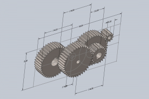
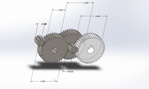
We decided to achieve this gear ratio by combining a 32:1 compound gear train with a 20:1 aluminium (or stainless steel) worm gear (bought from vendor) to both accommodate for the high ratio and a 90 degree torque transfer.
The compound gear design was made in Solidworks with a series of 4:1 and 2:1 gear ratios and motion simulations were run with ABS material properties to test resilience of a possibly 3d printed gearbox.
Some potential risks that remain with this design are inadequate gear shaft strength or inadequate gear meshing. Contingency plans for this part include:
-
-
- ordering gearboxes from only vendors
- although the high step down means that these are much rarer to attain and could prove more expensive and specialized for purposes that are not needed (such a much rotation rates or input torques)
- ordering gearboxes from only vendors
-
-
- Using a smaller step down ratio to turn a standard barn door mount as suggested by Joy. The solution would involve socket that would be turned with lower resolution than the (360 deg /86164 s) used for standard EQ mounts coupled with a device known as a barn door tracker that would provide much more fine tuned aiming. This would limit single capture length to around 10-20 minutes but would prove a lot more easily implementable.
My work for the week prior included implementing a library that would work backwards from telescope positioning to obtain the user’s equivalent coordinates. This is done by working backwards from known star positions and telescope displacement.
I also wanted to address the “Skychart” laser array for testing image drift and compensation. I was supposed to begin the process last week but I fell behind schedule and will be making it a priority next week in order to avoid further cascading. The design is simple but there are some design quirks that must be handled, like how to fabricate an appropriate grid for the laser light. Another thing that must be examined is if an average room is an appropriate projection surface for testing or if some hemispherical cover must be made on top of it.