The biggest risk right now is an incompatibility between the physical circuit and the software implementation in the final day of product implementation before the presentation is due. A difficulty in this aspect could prove to be a costly delay. This has been mitigated mostly by a good amount of software level verification from both Joy and Yuyi.
No changes in schedule have been made so far as the dominating factor this week is the presentation.
This week was mostly spent on getting the last few particulars of physical assembly done. Tomorrow (Sunday 26 2020) will mostly be spent on getting data and video compiled for the upcoming presentation. As of Saturday 4/25/2020 at 9:16 pm the progress on each individual physical part is as follows:
On top of that a few visual aids have been set up for debugging and demonstration purposes:
System Changes:
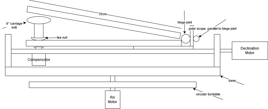
The main changes done this week basically break down to design changes to accommodate parts trickling in over time. Most of this is adapting the previous eq aligning design to the new barn door tracker. After receiving the universal stepper motor couplers I should be able to assemble the top portion of the diagram above with the exception of the motors since I do not have the pcb’s yet and I would like to thoroughly test them before placing them into the mount. Some things to point out in the diagram below include:
Progress has also been done in adapting logging for the Arduino. Getting the logger right now outputs to csv in real-time via a python script.
Risks:
Unfortunately, the arrival of the incorrect board types set back demo-readiness a fair bit, hopefully once the new boards arrived the new design will be ready for it. So that’s a risk that we could face.
Risks:
One major risk we’ve come across recently is that of a mix-up occurring during the shipping or ordering of items we order from the course staff. This week, instead of receiving the unipolar motor driver that was expected, we got an audio controller PCB from OSHPark. After a few days of inquiries, it was found that the PCB we received was in fact associated with another team’s design, and the course staff decided to re-order the board design. As a contingency for the delay caused by this particular mix-up, it was decided to order a set of darlington transistor arrays from Sparkfun to serve as a potential (if less effective) replacement for the PCB. As a contingency for future mix-ups, we intend to investigate alternatives to required components that can be physically picked up at a store by the team member responsible for assembling our project hardware.
System Updates:
Our previous design made use of an external touch enabled display to provide user interfacing with our raspi. However, in an attempt to reduce project complexity as well as to provide a contingency in the case that the raspi is not powerful enough to both compute image-based compensation on top of a GUI and touch screen feedback we will be altering the design. In our new altered design we will be emplogin a standard user-end notebook as the system for our GUI. This notebook will then communicate with the rpi via usart interfacing (alternatively via ethernet connection) and will provide the raspi with necessary user feedback and vice versa.
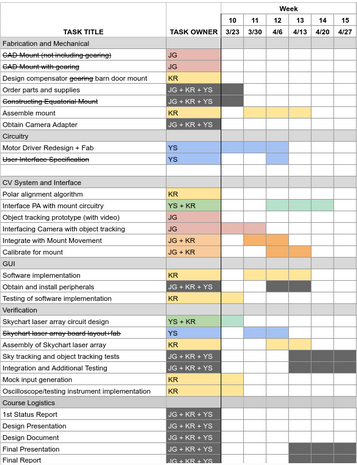
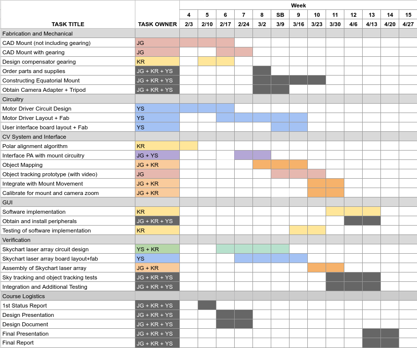
The above Gantt chart reflects the decision to move away from the usage of an external display to interface with users. Notably, the task labeled “User Interface Specification” has been struck through, indicating that it is no longer relevant for the project.
This week I worked on the tangent error calculations as well as the parametric equations for modeling the 3d piece used for hardware error correction.
Our new method of barn door tracker has inherent errors due to the way the upper arm is actuated (as the hypotenuse of a right triangle). This means that while the expected rotation rate should be constant the actual rotation that comes from this method is proportional to (dL/dt)where L is the rate of height change for the threaded rod.
This means that error from desire rate depends on arm length, thread pitch, and rate of thread rotation:
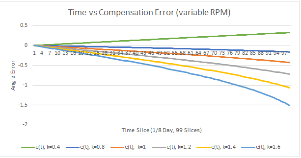
E(t) = (Sidereal Rate) * t – 2 * arcsin(k * t/60s * (thread_pitch) / (2 * arm_length))
Where k is rod rotation rate per minute.
Assuming a 200mm arm, a thread pitch of 1.27mm per rotation, and a sidereal rate of 2pi/86164s we get the following error:
E(t) = 2pi/86164s * t – 2 * arcsin(k * t/60s * (1.27)/(400mm))
Letting t E [0s, 10770.5s] (Or 1/8th of a sidereal day and ~ 3 hours) we get the following graphs for different rates k:
This provides the linear displacement perpendicular from the camera arm.
There are two methods for compensating for this: a software method and a 3d printed error compensator method.
The software method involves approximating the theta value necessary and working backwards to derive the necessary linear thread displacement. This can be easily implemented on the side along with the other motor drivers and could prove to have a smaller latency than the hardware method.
The hardware method for tangent error compensation involves using a constant rate for the thread motor and printing out a curve whose altitude is the negative of the error shown in the graphs above. In turn effectively reducing the error to 0. The only additional modeling requirement for this method is to find the parametric equation for parallel displacement which for pi/4 radians is L*(1 – cos(theta)) over [0, pi/4] radians and time of [0, 10770.5]s as before. Due to the fact that this is a piece that is on the bottom of the actuating arm we require that the error is negative throughout so we would go for constant k E [0.8, 1.6].
The advantages for using this method over the software method is that once the piece is printed the sidereal compensating motor only needs to be run at a constant rate and all of the error compensation is contained within the 3d printed piece.
Further updates:
The biggest risk we face right now is delays and assembly problems caused by the present pandemic. A lot of the testing that must be done normally requires specialty equipment that is not easily accessible outside of campus or prohibitively expensive. Similar issues are faced with assembly of the project including shipping times, equipment condition, and specialized tools. A lot of the changes we made during this week were in an effort to minimize the impact of these changes as well as lower the special requirements for assembly and construction that we relied on in the previous design. We will redesign the mount to reduce reliance on fabricated parts. This will take some time and put us somewhat behind.
We made a significant change to the original system design in switching to a barn door tracker-based design instead of a full equatorial mount. This was in response to the loss of access to fabrication facilities in light of the coronavirus situation, as the new design is mechanically simpler and is more easily constructed with standard components that can be shipped directly from McMaster. This change, and the implications for the capabilities we were aiming to support is fully detailed in our statement of work, which is attached here: http://course.ece.cmu.edu/~ece500/projects/s20-teamb1/wp-content/uploads/sites/83/2020/03/Statement-of-Work.pdf.
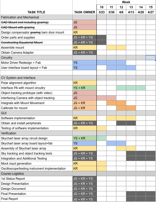
To reflect the change to the system design and the time lag caused by the uncertainties of our situation, we’ve updated the schedule:
One major change is that the majority of the assembly tasks have been delegated to Kenny. The actual integration of the various mount components will occur at his residence. Due to this, we have adjusted the division of other tasks to accommodate.
For this week there were some previously unexpected design changes due to the COVID-19 pandemic and the resulting quarantines and public space shutdowns. The more dramatic impacts include: our inability to physically coordinate, lack of access to Techspark, and lack of access to speciality testing or verifying equipment. Due to these changes a few changes had to be done to the “compensator” portion of our design. Many of these changes were listed in detail in the recent SOW.
The main tasks I tried to coordinate this week was getting the supplies necessary for assembly in my home. Since I will be the one doing physical assembly and testing I need access to a few specialized tools. Furthermore, for certain, less accessible or more expensive tools such as an oscilloscope I began researching an alternative in the “Arduino oscilloscope”. As our project partner Yuyi pointed out the frequencies at which the controller works at makes this option viable.
Another thing that I wanted to explore is using rendered images by simulating point light and point light movement in a spherical grid. Using these simulations we can create more accurate mock data as input for the pi. This should provide another alternative to testing which could come in handy in increasing input data fidelity without having to do field testing in the probable upcoming quarantines.
Risks:
On the electronic side of the project, there have been issues with shoot-through within the motor controller H-bridges. Since there are plans to tackle this issue in parallel with the task of producing a preliminary layout for the motor controller board, this means that we’ll need to modify said preliminary layout upon completion to reflect whichever changes are made to accommodate shoot-through protection circuitry. As a result, the earliest we can get the motor controller boards out to the fab is Spring Break (following a design review with one of the professors). Fortunately, there isn’t much of a risk of the issues being difficult to resolve, since shoot-through is a common problem with H-bridge circuits. The contingency in this case is to simply look up a shoot-through prevention circuit online and copy-paste it into the board layout.
Kenny isn’t on campus for the next week, so there will be a significant lag time with respect to communications. This could delay the work on the circuitry for the test setup by a week, which isn’t much of an issue since we still don’t have anything to use the test setup with. The contingency for this is for Kenny to simply look up a laser driver circuit online to implement (laser diodes just need a constant current driver, which consists of a resistively biased PNP transistor in its simplest form). The motor controllers for the test setup can be whichever commercial devices are compatible with servo motors/small stepper motors.
On the software side of the project, the CV may be too slow on a Raspberry Pi (as opposed to on a laptop computer). Down-sampling the images may help speed up object tracking on the Pi. The latency of image transfer between the user-provided camera and the Raspberry Pi is not likely to be an issue given that we are tracking slow-moving objects, but it may be too high to allow for real-time correction. In that case, we may have to implement blind tracking of objects. Although unlikely, details of translating between object velocities and pan-tilt of the mount may also present a problem. Restricting the camera’s position with respect to the mount may help simplify the problem.
On the mechanical side of the project, we had to redesign certain portions of the gearbox in order to fit the new ratio of the speed reducer, so while the risks are the same there has been less testing and simulation of the new design.
Schedule Changes:
As stated earlier, the completion deadline for the motor controller board has been pushed back a week to allow for the addition of shoot-through protection circuitry. The tasks relating to gyroscope circuit design/layout have been updated to omit all mentions to it, as we’ve decided to purchase a commercial gyroscope from Pololu with a pre-made breakout PCB.
As for the object detection it has been delayed a couple of weeks due to other parts of the project taking more time than previously envisioned. The changes reflected on the schedule is an overall 2 week delay on the object detection.
The updated Gantt chart is below:
For this week we made sure parts were ordered in hopes that we could start assembly the week after spring break. For the first half of the week we worked on fleshing out the report and budget making sure all part decisions were made. We decided that one of the stepper motor speed reducers we were looking into will probably be affected by shipping delays due to the rising COVID-19 epidemic and one of the backups I chose was for the wrong type of stepper motor so we had to respec the speed reduction ratio to 30:1 for NEMA 17 stepper motor. This means that I had to work on altering the reduction ratio of our compensator gearbox to a 43:2 for an effective ratio of 645:1 which is conveniently closer to our ideal 646:1 ratio than from our previous design although less of the speed reduction is being done with a well fabricated part and more with our own gearbox. For the rest of the week I was in between traveling and testing the polar axis alignment error calculator.