Risks:
On the electronic side of the project, there have been issues with shoot-through within the motor controller H-bridges. Since there are plans to tackle this issue in parallel with the task of producing a preliminary layout for the motor controller board, this means that we’ll need to modify said preliminary layout upon completion to reflect whichever changes are made to accommodate shoot-through protection circuitry. As a result, the earliest we can get the motor controller boards out to the fab is Spring Break (following a design review with one of the professors). Fortunately, there isn’t much of a risk of the issues being difficult to resolve, since shoot-through is a common problem with H-bridge circuits. The contingency in this case is to simply look up a shoot-through prevention circuit online and copy-paste it into the board layout.
Kenny isn’t on campus for the next week, so there will be a significant lag time with respect to communications. This could delay the work on the circuitry for the test setup by a week, which isn’t much of an issue since we still don’t have anything to use the test setup with. The contingency for this is for Kenny to simply look up a laser driver circuit online to implement (laser diodes just need a constant current driver, which consists of a resistively biased PNP transistor in its simplest form). The motor controllers for the test setup can be whichever commercial devices are compatible with servo motors/small stepper motors.
On the software side of the project, the CV may be too slow on a Raspberry Pi (as opposed to on a laptop computer). Down-sampling the images may help speed up object tracking on the Pi. The latency of image transfer between the user-provided camera and the Raspberry Pi is not likely to be an issue given that we are tracking slow-moving objects, but it may be too high to allow for real-time correction. In that case, we may have to implement blind tracking of objects. Although unlikely, details of translating between object velocities and pan-tilt of the mount may also present a problem. Restricting the camera’s position with respect to the mount may help simplify the problem.
On the mechanical side of the project, we had to redesign certain portions of the gearbox in order to fit the new ratio of the speed reducer, so while the risks are the same there has been less testing and simulation of the new design.
Schedule Changes:
As stated earlier, the completion deadline for the motor controller board has been pushed back a week to allow for the addition of shoot-through protection circuitry. The tasks relating to gyroscope circuit design/layout have been updated to omit all mentions to it, as we’ve decided to purchase a commercial gyroscope from Pololu with a pre-made breakout PCB.
As for the object detection it has been delayed a couple of weeks due to other parts of the project taking more time than previously envisioned. The changes reflected on the schedule is an overall 2 week delay on the object detection.
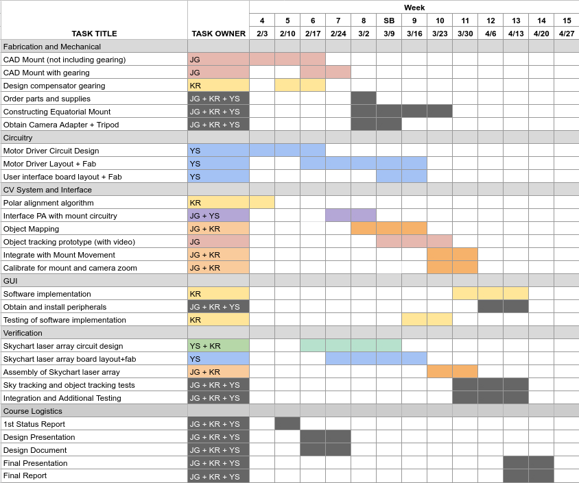
The updated Gantt chart is below: