This week I worked on the tangent error calculations as well as the parametric equations for modeling the 3d piece used for hardware error correction.
Our new method of barn door tracker has inherent errors due to the way the upper arm is actuated (as the hypotenuse of a right triangle). This means that while the expected rotation rate should be constant the actual rotation that comes from this method is proportional to (dL/dt)where L is the rate of height change for the threaded rod.
This means that error from desire rate depends on arm length, thread pitch, and rate of thread rotation:
E(t) = (Sidereal Rate) * t – 2 * arcsin(k * t/60s * (thread_pitch) / (2 * arm_length))
Where k is rod rotation rate per minute.
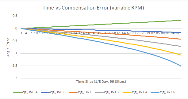
Assuming a 200mm arm, a thread pitch of 1.27mm per rotation, and a sidereal rate of 2pi/86164s we get the following error:
E(t) = 2pi/86164s * t – 2 * arcsin(k * t/60s * (1.27)/(400mm))
Letting t E [0s, 10770.5s] (Or 1/8th of a sidereal day and ~ 3 hours) we get the following graphs for different rates k:
This provides the linear displacement perpendicular from the camera arm.
There are two methods for compensating for this: a software method and a 3d printed error compensator method.
The software method involves approximating the theta value necessary and working backwards to derive the necessary linear thread displacement. This can be easily implemented on the side along with the other motor drivers and could prove to have a smaller latency than the hardware method.
The hardware method for tangent error compensation involves using a constant rate for the thread motor and printing out a curve whose altitude is the negative of the error shown in the graphs above. In turn effectively reducing the error to 0. The only additional modeling requirement for this method is to find the parametric equation for parallel displacement which for pi/4 radians is L*(1 – cos(theta)) over [0, pi/4] radians and time of [0, 10770.5]s as before. Due to the fact that this is a piece that is on the bottom of the actuating arm we require that the error is negative throughout so we would go for constant k E [0.8, 1.6].
The advantages for using this method over the software method is that once the piece is printed the sidereal compensating motor only needs to be run at a constant rate and all of the error compensation is contained within the 3d printed piece.
Further updates:
- I set up Arduino ADC logger that works through the Arduino IDE’s serial communicator.
- Most items that were shipped before spring break have arrived to my house so the only things that are left are our orders from last Friday that include motor/laser led controllers/drivers and further structural pieces.
- This week I will be setting up for measuring some of the demos possible as well as discussing our options for tangent error compensation.