Parts that might be falling behind
The selection of an appropriate gyroscope sensor was originally scheduled for this week, but complications with circuit simulation for the motor controller circuit have prevented us from working on it. Fortunately, we are still in compliance with the Gantt chart schedule for this (circuit design isn’t really required for the gyroscope sensor), and we still have a few weeks set out for board layout.
Risk mitigation
There is a risk that our fabrication schedule will fall behind due to some delays and our being unfamiliar with the logistics of doing fab work through capstone. Some solutions to get around queue times/techspark issues would be to go through different venues and simply acquire the material through capstone but the machines through outside organizations like Roboclub.
As far as delays accrued over other portions of the project the only real solution is to revise our schedule after the main set of fabrication is done to more easily catch up on unforeseen complexity.
Additionally, there is a chance that the motor controller PCB will experience catastrophic failure when turned on. We’ve been calculating expected power dissipation/maximum voltages using SPICE simulation for the components to ensure that the components we selected will never exceed their maximum ratings, but simulations don’t truly account for component variations. Furthermore, we’ve only been performing circuit simulations — EM simulation is out of the project scope, so the PCB layout may very well degrade the circuit performance to the point that components are stressed past their ratings.
Furthermore, the propagation delays for the motor controller pins could be significantly higher than simulated, producing complications for the programming phase of this project. There isn’t much that can be done about this — data on the digital components of the motor controller circuit is extremely limited and the models we do have appear to be simplistic.
Schedule Adjustments
Right now most of our focus is going towards finalizing fabrication but that was accounted for in the original schedule with several weeks of slack to compensate.
Progress Photos
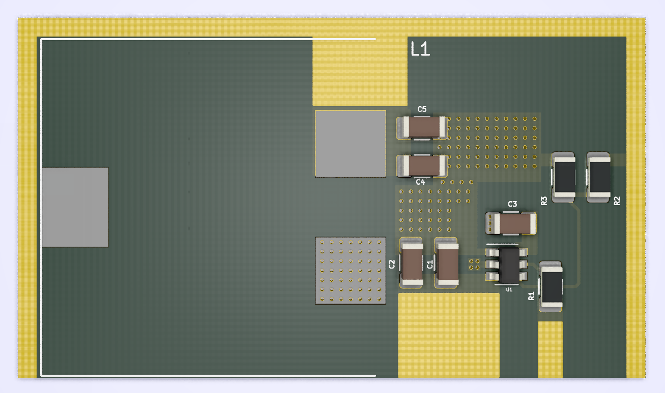
Here’s a 3D render of the 3V SMPS standard cell that was laid out this week for powering our project’s stepper motors. This module can be easily integrated into the final layout for the motor controllers by copy-pasting it in. The 3V output is accessible on 3 sides of the cell, making it more flexible to use during the place and route process.