Joy’s Status Update for 2020-02-15

My tasks for the week:

  • Design the mount (not including gearing)
  • CAD the mount (not including gearing) in SolidWorks
  • Figure out which parts must be purchased
  • Figure out how to fabricate remaining parts

What I have from this week:

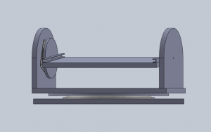
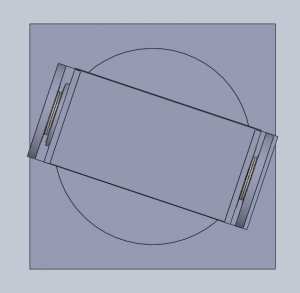
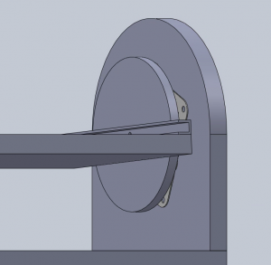
  • A very rough SolidWorks assembly of the mount
    • Fasteners, some gears, some teeth on gears omitted
    • Tentative dimensions
    • There is an upper part of the mount that includes Kenny’s compensator gearbox, which is relatively complicated and may take up a bit of space. I have not drawn it because I am not sure how it will fit in.
  • A partial list of parts to purchase
    • From McMaster-Carr
      • 2 square turntables (6031K160)
      • 1 round turntables (1544T200)
      • 4″ of aluminum U-channel (9001K124)
        • Or maybe a different size
    • Still need to figure out what screws and other fasteners we need
  • Ideas for fabrication of other parts
    • MDF panels, which can be jigsawed
    • Gears lasercut from quarter-inch-thick HDPE
      • IDeATe doesn’t allow HDPE in its laser-cutters, but TechSpark does.
      • HDPE can be tricky to cut, melting or catching fire on the wrong settings.

My progress:

  • I am mostly on schedule. I am not completely satisfied with the design, and there are some uncertainties, but next week is also allocated to improving the CAD and integrating it with Kenny’s gearing designs.
  • I am a bit behind. I still need to figure out what size aluminum U-channel, which screws and fasteners, etc. that we require for the mount. I would like to improve the CAD so that it has more detail (e.g., the holes that must be drilled into the MDF panels). I still have not asked my team members for feedback and suggestions.
  • How I will catch up: I have Sunday and Monday to figure out parts and improve the CAD.

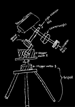
Challenges/Requirements for the mount:

  • Holding up the weight of the photographing equipment as well as the polar aligned compensator.
  • Having enough space to accomodate the equipment and the polar aligned compensator.
  • Having the 0.5 degree accuracy when positioning.
  • Having the torque necessary to lift the equipment and compensator.

Next week:

  • Talk to team members about the design.
  • Order parts and talk to the right people about fabrication credits for the team.
  • Figure out with Kenny how the gearing will integrate with the rest of the mount.
  • CAD the mount in more detail.

Team Status Update for 15 Feb. 2020

At this point in the project, we’ve come across risks on both the electronic and mechanical side of the project. If the H-bridge controllers for each of the equatorial mount’s stepper motors are switched improperly, it’s possible for the transistors in the H-bridges to short the motors’ power supplies. The result would be burned transistors, a dead buck-converter IC, and burned out inductors. In the worst case, the PCBs on which the H-bridges are mounted could overheat and blow out. If the traces associated with the H-bridge transistors and gate driver ICs are too long, the parasitic inductance could generate voltage spikes that’ll eventually kill the transistors.

Some of the most critical mechanical challenges are mostly down to the dynamics of the mount. We need to provide accurate enough actuation without going over budget or over scope. Inaccurate fabrication and design could lead to a large discrepancy between our model and our actual mount which leads to higher and unpredictable errors in the final product. A lot of our accuracy is derived from how well we design the gearing at each joint and how well we can predict errors to allow for a lower fabrication cost.

The risks on the electronic component of this project can be managed through careful layout practices and the usage of circuitry to prevent the appearance of inappropriate control signals at the H-bridge inputs (such as an inverter between inputs that are known to be complementary).

The risks of the mechanical component of the project can be managed through careful prototyping and simulation. Contingency plans have also been discussed for the more complex and error prone portions of the fabrication.

Fortunately, we have not seen fit to make changes to the existing design of the system this week. None of the design challenges we tackled in order to meet the design specifications we set earlier were impossible or infeasible.

We’re planning to use a week of slack time (that was already allocated in our initial Gantt chart) to finish up the circuit design for the equatorial mount’s motor drivers and gyroscope sensor. Otherwise, there have been no changes to our plans.

At this point, we’ve specified parts for the mount motors’ power supplies, and have selected components for the motor driver circuits:


LtSpice simulation has also been used to characterize the motor driver designs for propagation delay in preparation for programming the Raspberry Pi:

The general structure of our mount has been laid out in SolidWorks:

Introduction and Project Summary

Stars, planets, and the assorted astronomical objects that are visible in the night sky are dim. This makes life difficult for any intrepid photographers that seek to capture them for posterity, as camera sensors/film must be exposed for several seconds to detect all but the brightest objects. Any changes in the position of the camera lens relative to the starscape can smear the stars across the camera sensor, producing streaks of starlight in the final image. Since the majority of this movement comes from the rotation of the Earth around its axis, astrophotographers use motorized camera mounts to rotate their cameras with the Earth. These equatorial mounts rotate cameras at a speed that is set by the user, exposing them to human error and making their setup procedure rather inconvenient. Furthermore, the majority of equatorial mounts that are affordable for amateur astrophotographers are incapable of tracking the movements of nearby objects (planets and comets) that move relative to the starscape.

We aim to resolve both of these issues with Asterism. Asterism is an equatorial mount whose motors are linked to the camera through a computer vision routine, enabling it to automatically calibrate the speed with which it rotates the user’s camera. A second mode of the computer vision routine will allow it to track individual objects that move relative to the stars. This is a significant, and most importantly, affordable step up from the budget equatorial mounts that are commonly used by amateur astrophotographers.

The details of our proposal are linked here.