At this point in the project, we’ve come across risks on both the electronic and mechanical side of the project. If the H-bridge controllers for each of the equatorial mount’s stepper motors are switched improperly, it’s possible for the transistors in the H-bridges to short the motors’ power supplies. The result would be burned transistors, a dead buck-converter IC, and burned out inductors. In the worst case, the PCBs on which the H-bridges are mounted could overheat and blow out. If the traces associated with the H-bridge transistors and gate driver ICs are too long, the parasitic inductance could generate voltage spikes that’ll eventually kill the transistors.
Some of the most critical mechanical challenges are mostly down to the dynamics of the mount. We need to provide accurate enough actuation without going over budget or over scope. Inaccurate fabrication and design could lead to a large discrepancy between our model and our actual mount which leads to higher and unpredictable errors in the final product. A lot of our accuracy is derived from how well we design the gearing at each joint and how well we can predict errors to allow for a lower fabrication cost.
The risks on the electronic component of this project can be managed through careful layout practices and the usage of circuitry to prevent the appearance of inappropriate control signals at the H-bridge inputs (such as an inverter between inputs that are known to be complementary).
The risks of the mechanical component of the project can be managed through careful prototyping and simulation. Contingency plans have also been discussed for the more complex and error prone portions of the fabrication.
Fortunately, we have not seen fit to make changes to the existing design of the system this week. None of the design challenges we tackled in order to meet the design specifications we set earlier were impossible or infeasible.
We’re planning to use a week of slack time (that was already allocated in our initial Gantt chart) to finish up the circuit design for the equatorial mount’s motor drivers and gyroscope sensor. Otherwise, there have been no changes to our plans.
At this point, we’ve specified parts for the mount motors’ power supplies, and have selected components for the motor driver circuits:
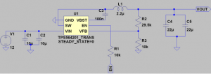
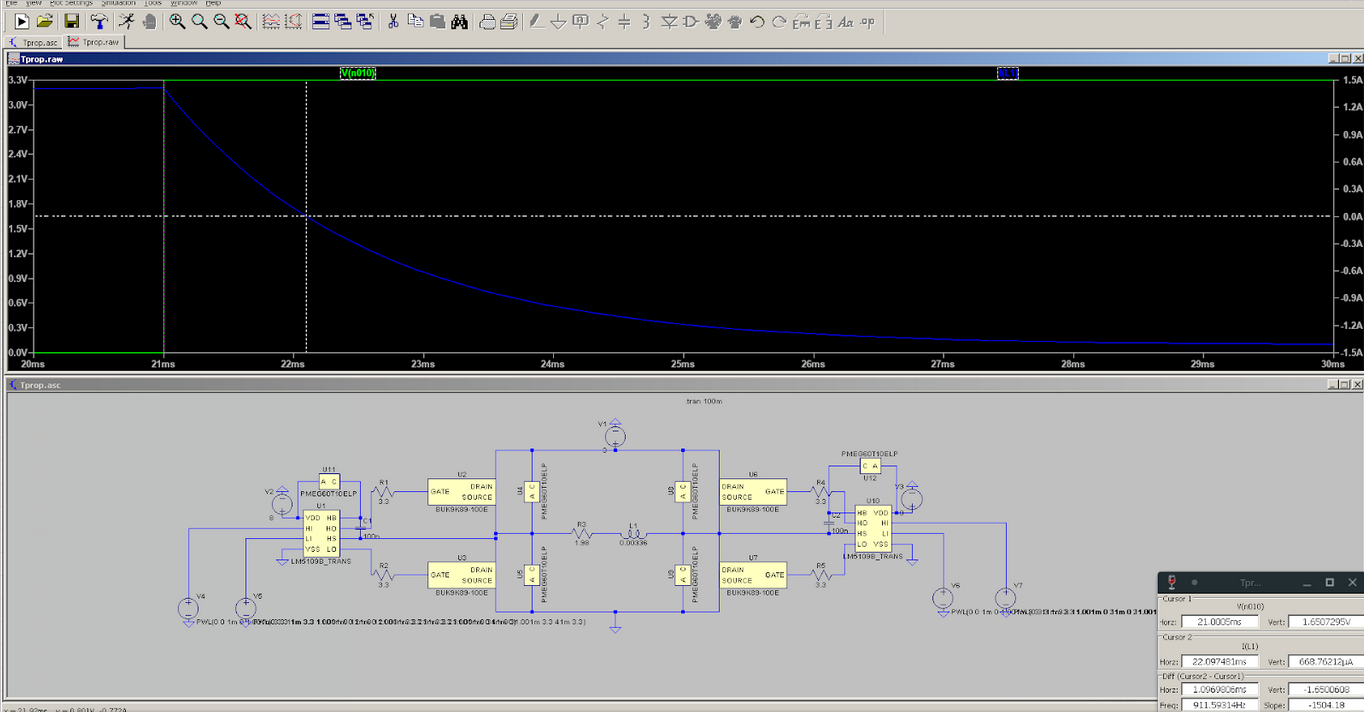
LtSpice simulation has also been used to characterize the motor driver designs for propagation delay in preparation for programming the Raspberry Pi:
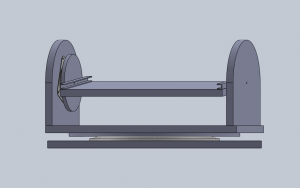
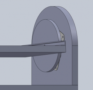
The general structure of our mount has been laid out in SolidWorks: