Kenny Ramos’s Status update for 22 Feb. 2020

Kenny Ramos’s Status update for 22 Feb. 2020:

For this week I began setup work for computer vision and object recognition as well as the rest of the basic RPI toolchains that will be necessary for the project. Most of my time on this was spent setting up RPI, compiling libraries, setting up OpenCV, testing MTP protocols with libgphoto2, setting up cpp interfacing with libgphoto2, and some very annoying RPI quirks.


Compiling linux libraries and setting up RPI specific stuff is pretty mundane so I will go over the library lists needed to compile as well as some preliminary tests that I ran to make sure it responded well.


Libraries Used (for now):


Preliminary Tests:

For OpenCV testing is fairly simple since it comes with a set of examples that it is ready to run. Testing should be done later to measure performance. For libgphoto2 I simply tested compatibility with my phone (Galaxy S9 that supports [MTP](https://docs.microsoft.com/en-us/windows/iot-core/connect-your-device/mtp))


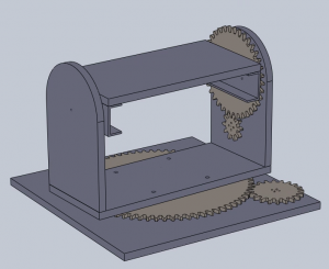
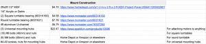
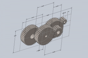
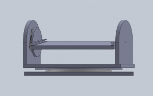
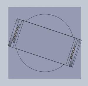
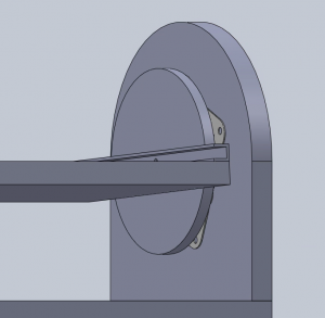
Another task I had to setup this week was trying to figure out how to fabricate parts in the techspark space as well as collaborate with Joy in order to interface the parts I am fabricating with the stand she is working on. I asked around techspark about getting funds or materials for Capstone projects but I think I need to ask the professors and TA’s in more detail next week. Furthermore, the interfacing will probably be held until next week as well.


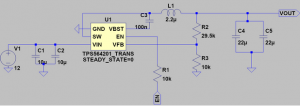
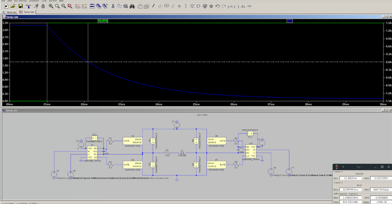
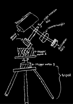
A final task that I planned on starting concretely for this week was getting the testing rigs (mainly the star projector) started. I finalized the block diagram and overall plan but I wasn’t able to start the modeling and simulation portion as of yet due to delays from setting up software as well as working on design review presentations. I plan to make up most of this lag next week assuming that our Design Review presentation is rugged enough to make the Design review report easier to finalize. If this is not the case I might have to put in some time towards the end of next week to try to get this done before spring break.

For risks I don’t foresee any more structural/implementation problems that could arise (other than the ones discussed last week). The only new risks are operational and managerial ones in the forms of delay and lack of sync that should get handled by more rigorous attention to checkpoints set by our schedule.


For next week the plan is to flesh out the testing rig in solidworks and finally get things on the compensator side fabricated so that I can start integration with other team members. With the RPI setup and working properly that can go into the backburner for next week in the interest of finalizing fabrication.


Team Status Update for 22 Feb. 2020

Parts that might be falling behind

The selection of an appropriate gyroscope sensor was originally scheduled for this week, but complications with circuit simulation for the motor controller circuit have prevented us from working on it. Fortunately, we are still in compliance with the Gantt chart schedule for this (circuit design isn’t really required for the gyroscope sensor), and we still have a few weeks set out for board layout.

Risk mitigation

There is a risk that our fabrication schedule will fall behind due to some delays and our being unfamiliar with the logistics of doing fab work through capstone. Some solutions to get around queue times/techspark issues would be to go through different venues and simply acquire the material through capstone but the machines through outside organizations like Roboclub.

As far as delays accrued over other portions of the project the only real solution is to revise our schedule after the main set of fabrication is done to more easily catch up on unforeseen complexity.

Additionally, there is a chance that the motor controller PCB will experience catastrophic failure when turned on. We’ve been calculating expected power dissipation/maximum voltages using SPICE simulation for the components to ensure that the components we selected will never exceed their maximum ratings, but simulations don’t truly account for component variations. Furthermore, we’ve only been performing circuit simulations — EM simulation is out of the project scope, so the PCB layout may very well degrade the circuit performance to the point that components are stressed past their ratings.

Furthermore, the propagation delays for the motor controller pins could be significantly higher than simulated, producing complications for the programming phase of this project. There isn’t much that can be done about this — data on the digital components of the motor controller circuit is extremely limited and the models we do have appear to be simplistic.

Schedule Adjustments

Right now most of our focus is going towards finalizing fabrication but that was accounted for in the original schedule with several weeks of slack to compensate.

Progress Photos

Here’s a 3D render of the 3V SMPS standard cell that was laid out this week for powering our project’s stepper motors. This module can be easily integrated into the final layout for the motor controllers by copy-pasting it in. The 3V output is accessible on 3 sides of the cell, making it more flexible to use during the place and route process.

Joy’s Status Update for 2020-02-22

My tasks for the week:

  • Talk to team members about the design.
  • Order parts and talk to the right people about fabrication credits for the team.
  • Figure out with Kenny how the gearing will integrate with the rest of the mount.
  • CAD the mount in more detail.
  • If time: start on object tracking demo.

What I did this week:

  • Figured out how to attach the compensator gearbox to the rest of the mount. We plan to hold the gears in place within an acrylic box with threaded rods, bearings, nuts, and spacers.
  • CAD the mount in more detail. [ todo insert image ]
  • Work out a more detailed parts list, down to screw sizes etc. [ todo screenshot the spreadsheet ]
  • Worked on design slides with team.

My progress:

  • I am somewhat behind.
  • I didn’t order parts or get information about fabrication credits for the team. This is bad because it pushes back when we can start on mechanical construction.
  • I also hoped to start on the object tracking demo. I didn’t.

Next week:

  • I would like to catch up on ordering parts and getting information about fabrication credits.
  • I would like to start on the object tracking demo. Like Kenny did this week, in Week 7, I will be installing OpenCV (locally, not on the Pi yet). I will be attempting to create a demo for object tracking. I will test it with video samples. Currently, I don’t know what kind of quantitative result would be considered “passing,” but the purpose of this software prototype is to figure out how small the resolution of the images can be before the performance of the object tracking decreases dramatically.

Kenny Ramos’s Status Update 02.15.20

For this week I began work on the rotational velocity step down for the Polar rotation compensator. In order to properly compensate for the rate of rotation observed in the night sky the final rate of rotation for the mount must be an average of (1 Rev/Sidereal Day) or about (360 deg/86,164s). The highest resolution stepper motor we found within our range managed (400 steps/rev) so it was necessary to step it down by at least a ratio of (86,164/400 =  215.41 ~ 215.5 = 531:2) to achieve proper output rate given a stepper motor rate of 1 step per second.

We decided to attempt a step down of 640 at a stepper motor rate of 3 steps per second. This would produce a ~1% error in the rotational displacement of the equatorial mount from the target which is more than acceptable and can even be corrected for once the error accumulates to ⅓ of the effective step output (that is to say the distance that the final portion of the mount is moved for every step of the motor). This correction would be done by occasionally adding one leap step when this ⅓ metric is reached.

We decided to achieve this gear ratio by combining a 32:1 compound gear train with a 20:1 aluminium (or stainless steel) worm gear (bought from vendor) to both accommodate for the high ratio and a 90 degree torque transfer.

The compound gear design was made in Solidworks with a series of 4:1 and 2:1 gear ratios and motion simulations were run with ABS material properties to test resilience of a possibly 3d printed gearbox.

Some potential risks that remain with this design are inadequate gear shaft strength or inadequate gear meshing. Contingency plans for this part include:

      • ordering gearboxes from only vendors
        • although the high step down means that these are much rarer to attain and could prove more expensive and specialized for purposes that are not needed (such a much rotation rates or input torques)
    • Using a smaller step down ratio to turn a standard barn door mount as suggested by Joy. The solution would involve socket that would be turned with lower resolution than the (360 deg /86164 s) used for standard EQ mounts coupled with a device known as a barn door tracker that would provide much more fine tuned aiming. This would limit single capture length to around 10-20 minutes but would prove a lot more easily implementable.


My work for the week prior included implementing a library that would work backwards from telescope positioning to obtain the user’s equivalent coordinates. This is done by working backwards from known star positions and telescope displacement.


I also wanted to address the “Skychart” laser array for testing image drift and compensation. I was supposed to begin the process last week but I fell behind schedule and will be making it a priority next week in order to avoid further cascading. The design is simple but there are some design quirks that must be handled, like how to fabricate an appropriate grid for the laser light. Another thing that must be examined is if an average room is an appropriate projection surface for testing or if some hemispherical cover must be made on top of it.

Yuyi Shen’s Status Update for 15 Feb. 2020

My tasks for this week were to finish designing the circuits for the equatorial mount’s stepper motor drivers and gyroscope. To this end, I have finished designing a buck converter circuit for supplying each stepper motor with 3V (and a maximum of 4A) from the 12 V supply voltage that we’re expecting:

Furthermore, I’ve set up a bill of materials on Digikey for the design: https://www.digikey.com/short/z3w1wm. One assembly costs $8.22.

I have also specified appropriate components for the H-bridge circuits that will ultimately interface with the stepper motor coils:

The MOSFETs were selected to have an on-resistance that’s 20 times less than the stepper motor’s worst-case series resistance spec so that they wouldn’t overly impact the current drawn from the motor power supply by the stepper motor coil. Similarly, the flyback diodes were chosen to have an on-resistance that’s on the order of the stepper motor coil’s series resistance so that they could effectively dissipate voltage spikes from the coil’s inductance. Lastly, the gate driver ICs were chosen to be compatible with 3.3V logic, as the Raspberry Pi has 3.3V GPIO pins.

To confirm my component selections, I ran LtSpice simulations to gauge the power dissipated by the flyback diodes if a single lo-side or hi-side MOSFET abruptly turned off (the worst case scenario in the context of kickback voltage transients). LtSpice simulation indicates that individual flyback diodes will dissipate a worst-case value of 754 uJ over 3.2 ms if a low side MOSFET suddenly fails open while passing current from the stepper motor coil. This corresponds to a power level of 0.24 W, which is about a third of the flyback diode’s maximum power dissipation. Therefore, the diodes that were selected will likely survive normal operation.

To facilitate my teammates’ work with the Raspberry Pi, I used LtSpice to characterize the propagation delay from the voltage at the hi-side input of one of the H-bridge’s gate driver ICs to the current passing through the stepper motor (modeled here as a series RL circuit). I found that the propagation delay for a falling edge at the hi-side input of a gate driver was roughly 1.08 ms, while the propagation delay for a rising edge at the hi-side gate driver input was 1.09 ms. This is very close to the theoretical propagation delay that can be calculated from the L/R ratio of the stepper motor coil (ln(2)*time constant), 1.2 ms. This means that the MOSFETs that I selected for the H-bridge will likely be effective at driving the equatorial mount’s stepper motors.

Unfortunately, I am behind schedule. To get back on track, I’ll need to find an appropriate gyroscope for the equatorial mount and design an interface circuit, and put the finishing touches on the stepper motor driver circuit. The former should be a fairly trivial task (most sensor datasheets will have a recommended circuit for facilitating the sensor’s interface), but the latter will consist of two significant tasks: designing an 8 V switched mode power supply for the H-bridge’s gate driver ICs and developing a chain of fast logic gates to convert the 4 H-bridge inputs into a pair of inputs (one enable input and one control input).

Next week, I intend to finish the stepper motor driver circuit. Given the time it took for me to simulate the fundamental H-bridge setup in LtSpice, I estimate that this will take at least half the week. Furthermore, since I’m scheduled to begin laying out the PCBs next week, I’ll aim to finish the layout for the 3V power supply that I designed this week for the motors.

The primary risk to this objective is the development of a logic chain for transforming the H-bridge inputs into a single control input for use with the Raspberry Pi that we plan to use for controlling the equatorial mount. Propagation delays for each of the 4 H-bridge inputs will need to be matched, which is a relatively difficult task to achieve. My contingency plan is to simply omit the logic chain altogether. This approach will use up more GPIO pins on the Pi, but is more likely to function.

Joy’s Status Update for 2020-02-15

My tasks for the week:

  • Design the mount (not including gearing)
  • CAD the mount (not including gearing) in SolidWorks
  • Figure out which parts must be purchased
  • Figure out how to fabricate remaining parts

What I have from this week:

  • A very rough SolidWorks assembly of the mount
    • Fasteners, some gears, some teeth on gears omitted
    • Tentative dimensions
    • There is an upper part of the mount that includes Kenny’s compensator gearbox, which is relatively complicated and may take up a bit of space. I have not drawn it because I am not sure how it will fit in.
  • A partial list of parts to purchase
    • From McMaster-Carr
      • 2 square turntables (6031K160)
      • 1 round turntables (1544T200)
      • 4″ of aluminum U-channel (9001K124)
        • Or maybe a different size
    • Still need to figure out what screws and other fasteners we need
  • Ideas for fabrication of other parts
    • MDF panels, which can be jigsawed
    • Gears lasercut from quarter-inch-thick HDPE
      • IDeATe doesn’t allow HDPE in its laser-cutters, but TechSpark does.
      • HDPE can be tricky to cut, melting or catching fire on the wrong settings.

My progress:

  • I am mostly on schedule. I am not completely satisfied with the design, and there are some uncertainties, but next week is also allocated to improving the CAD and integrating it with Kenny’s gearing designs.
  • I am a bit behind. I still need to figure out what size aluminum U-channel, which screws and fasteners, etc. that we require for the mount. I would like to improve the CAD so that it has more detail (e.g., the holes that must be drilled into the MDF panels). I still have not asked my team members for feedback and suggestions.
  • How I will catch up: I have Sunday and Monday to figure out parts and improve the CAD.

Challenges/Requirements for the mount:

  • Holding up the weight of the photographing equipment as well as the polar aligned compensator.
  • Having enough space to accomodate the equipment and the polar aligned compensator.
  • Having the 0.5 degree accuracy when positioning.
  • Having the torque necessary to lift the equipment and compensator.

Next week:

  • Talk to team members about the design.
  • Order parts and talk to the right people about fabrication credits for the team.
  • Figure out with Kenny how the gearing will integrate with the rest of the mount.
  • CAD the mount in more detail.

Team Status Update for 15 Feb. 2020

At this point in the project, we’ve come across risks on both the electronic and mechanical side of the project. If the H-bridge controllers for each of the equatorial mount’s stepper motors are switched improperly, it’s possible for the transistors in the H-bridges to short the motors’ power supplies. The result would be burned transistors, a dead buck-converter IC, and burned out inductors. In the worst case, the PCBs on which the H-bridges are mounted could overheat and blow out. If the traces associated with the H-bridge transistors and gate driver ICs are too long, the parasitic inductance could generate voltage spikes that’ll eventually kill the transistors.

Some of the most critical mechanical challenges are mostly down to the dynamics of the mount. We need to provide accurate enough actuation without going over budget or over scope. Inaccurate fabrication and design could lead to a large discrepancy between our model and our actual mount which leads to higher and unpredictable errors in the final product. A lot of our accuracy is derived from how well we design the gearing at each joint and how well we can predict errors to allow for a lower fabrication cost.

The risks on the electronic component of this project can be managed through careful layout practices and the usage of circuitry to prevent the appearance of inappropriate control signals at the H-bridge inputs (such as an inverter between inputs that are known to be complementary).

The risks of the mechanical component of the project can be managed through careful prototyping and simulation. Contingency plans have also been discussed for the more complex and error prone portions of the fabrication.

Fortunately, we have not seen fit to make changes to the existing design of the system this week. None of the design challenges we tackled in order to meet the design specifications we set earlier were impossible or infeasible.

We’re planning to use a week of slack time (that was already allocated in our initial Gantt chart) to finish up the circuit design for the equatorial mount’s motor drivers and gyroscope sensor. Otherwise, there have been no changes to our plans.

At this point, we’ve specified parts for the mount motors’ power supplies, and have selected components for the motor driver circuits:


LtSpice simulation has also been used to characterize the motor driver designs for propagation delay in preparation for programming the Raspberry Pi:

The general structure of our mount has been laid out in SolidWorks:

Introduction and Project Summary

Stars, planets, and the assorted astronomical objects that are visible in the night sky are dim. This makes life difficult for any intrepid photographers that seek to capture them for posterity, as camera sensors/film must be exposed for several seconds to detect all but the brightest objects. Any changes in the position of the camera lens relative to the starscape can smear the stars across the camera sensor, producing streaks of starlight in the final image. Since the majority of this movement comes from the rotation of the Earth around its axis, astrophotographers use motorized camera mounts to rotate their cameras with the Earth. These equatorial mounts rotate cameras at a speed that is set by the user, exposing them to human error and making their setup procedure rather inconvenient. Furthermore, the majority of equatorial mounts that are affordable for amateur astrophotographers are incapable of tracking the movements of nearby objects (planets and comets) that move relative to the starscape.

We aim to resolve both of these issues with Asterism. Asterism is an equatorial mount whose motors are linked to the camera through a computer vision routine, enabling it to automatically calibrate the speed with which it rotates the user’s camera. A second mode of the computer vision routine will allow it to track individual objects that move relative to the stars. This is a significant, and most importantly, affordable step up from the budget equatorial mounts that are commonly used by amateur astrophotographers.

The details of our proposal are linked here.