Yuyi Shen’s Status Update for March 7 2020

This week, I worked on generating a preliminary layout for the motor controller board in KiCad. To accomplish this, I finished specifying and laying out an 8V LDO-based supply for the motor controller ICs:

It’s laid out in standard-cell format so that it can be easily dropped into the final motor controller board. We came up with an initial BOM for this supply for the design report, but I ended up revising it to better reflect the requirements stated in the voltage regulator’s datasheet: https://www.digikey.com/short/z8pr24. The revised BOM simply includes two large I/O capacitors, so there isn’t much of a change to the budget. The specific IC is the LK112M80TR (rated for 150 mA of output current). Fortunately, the low quiescent current draw of the motor driver ICs (22.8 mA in total for each controller board) means that we don’t need to include thermal considerations during layout design. It takes a 23.5 C temperature rise to produce a 1dB degradation of supply voltage rejection for this particular regulator (the key spec for a LDO), and it’s incredibly difficult to produce that with only 91 mW of quiescent power consumption.

I’ve also produced a PDF of the tentative full schematic for the motor controller: KiCad Schematic

At the moment, the layout of the motor controller board is being held up by the unwieldy footprints of the MOSFETs. Each MOSFET drain requires a 28 mm by 28 mm copper square to keep their temperatures below ~35 C during operation, resulting in this horrid thing:

It doesn’t help that the MOSFET drains are on one side of the package while the sources and gates are on the other, since drains and sources need to be connected in a H-bridge. I’ve gotten around this thus far by using one MOSFET in each IC (the ICs have 2 MOSFETs each) for individual half-bridges, but it requires excessive distance between the MOSFET gates and gate drivers (terrible for minimizing H-bridge ringing).

Luckily, there haven’t been any issues with copy-pasting the standard cells for the power supplies into the full motor controller KiCad project. I was initially worried when I figured out that it’s not possible to directly copy-paste between KiCad instances, but it turns out that EESchema allows users to append schematics, while the standalone version of PCBnew allows for appending layouts.

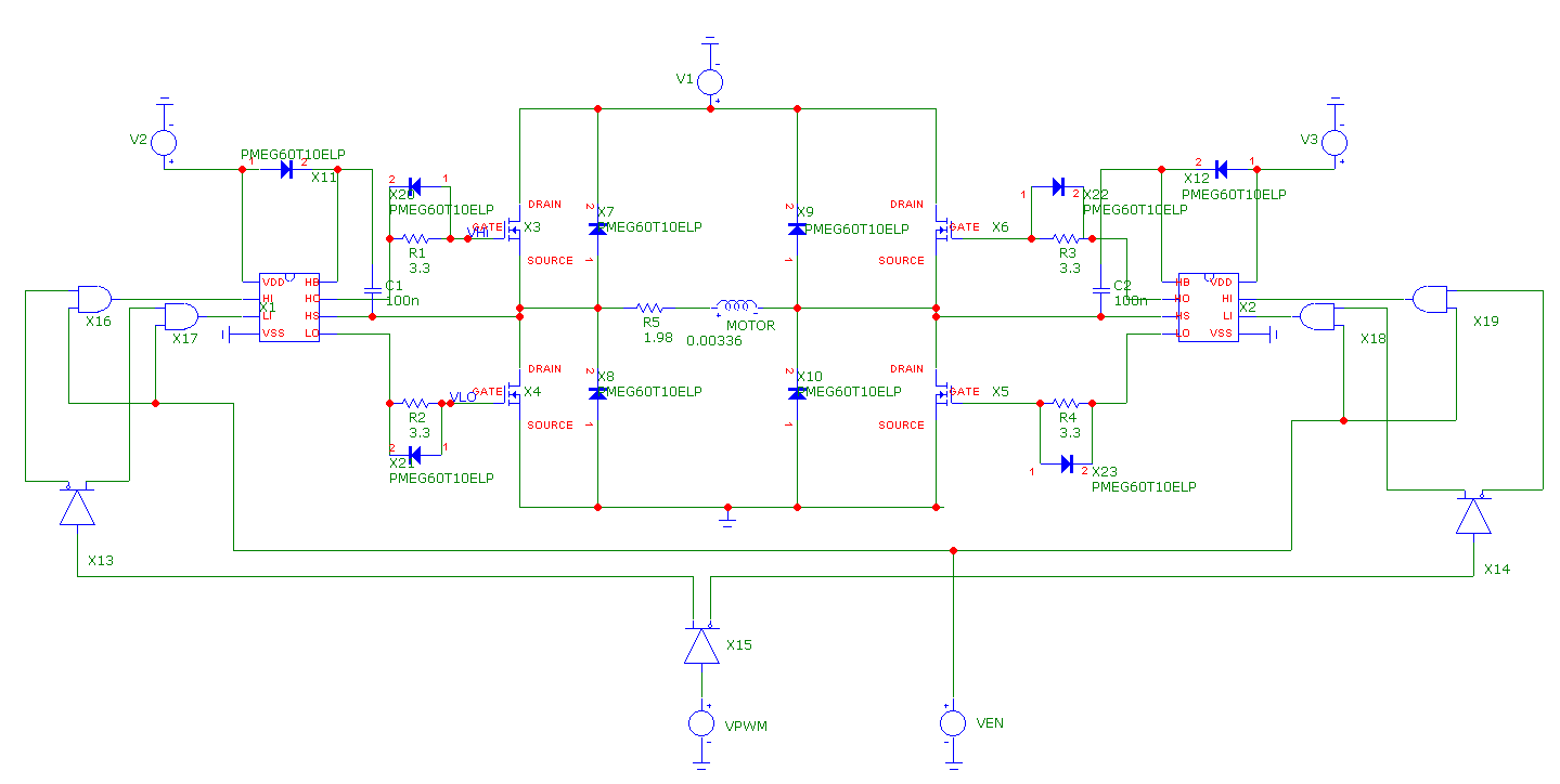
I’ve also run a new simulation of the H-bridge, with diodes placed at the MOSFET gates to speed up turn-off times and hopefully prevent shoot-through:

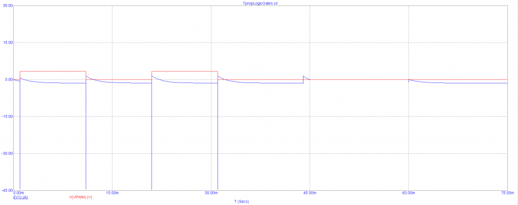
Unfortunately, simply placing the diodes there does little to prevent shoot-through, as can be seen in this simulation of the power supply current (the blue waveform) as the H-bridge is switched:

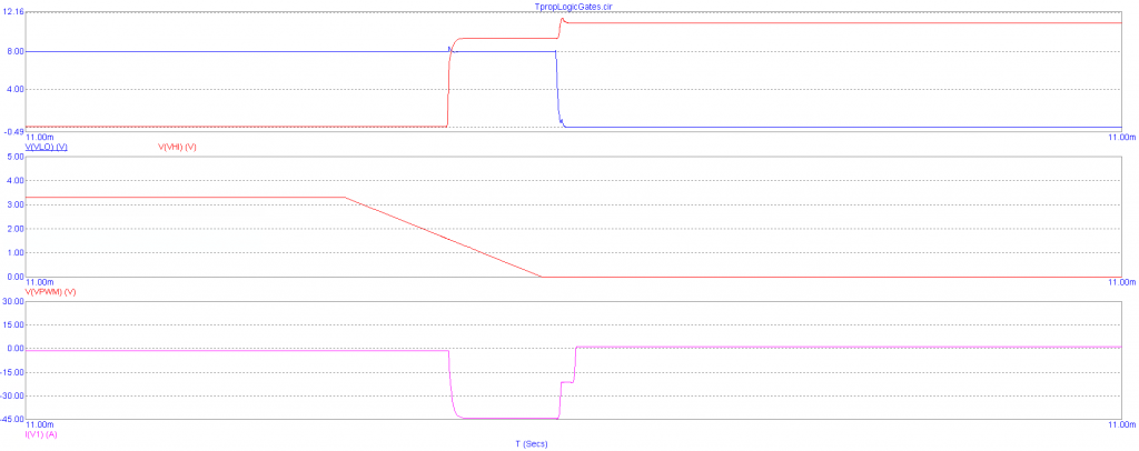
Clearly, there are immense current spikes exceeding 45A in amplitude as the motor controller PWM input is turned on and off. Simulating for the gate voltages of the hi and low-side MOSFETs on the “left” side of the H-bridge confirms that these spikes are caused by shoot-through:

The voltage at the MOSFET gates (the top set of waveforms) is high for both hi-side and lo-side MOSFETs for a short amount of time, causing the MOSFETs to short the supply to ground temporarily.

I’m behind by a week. I resolved to complete the motor controller board by the first half of this week, but was delayed by a series of unfortunate events (design report due on Monday, design review for another class, and an Open House event for prospective grad students). To catch up, I’ll need to resolve the shoot-through issues in simulation (hopefully through simply finding a circuit to copy-paste). Then, I’ll need to wrestle with the MOSFET footprints and find a way to position them so as to avoid adding extreme amounts of parasitic inductance into the gate driver traces. Lastly, I’ll need to talk with Kenny about what the circuitry for the test-setup should look like (so that he can do the actual design by himself, and perform sanity checks against our general expectations).

Next week, I hope to complete the layout for the motor controller board, and meet with one of the professors to perform a design review (probably in the latter half of the week). Given the challenges that this part of the project has posed thus far, I think that’s the most I can hope for.

Team Status Update for March 7 2020

Risks:

On the electronic side of the project, there have been issues with shoot-through within the motor controller H-bridges. Since there are plans to tackle this issue in parallel with the task of producing a preliminary layout for the motor controller board, this means that we’ll need to modify said preliminary layout upon completion to reflect whichever changes are made to accommodate shoot-through protection circuitry. As a result, the earliest we can get the motor controller boards out to the fab is Spring Break (following a design review with one of the professors). Fortunately, there isn’t much of a risk of the issues being difficult to resolve, since shoot-through is a common problem with H-bridge circuits. The contingency in this case is to simply look up a shoot-through prevention circuit online and copy-paste it into the board layout.

Kenny isn’t on campus for the next week, so there will be a significant lag time with respect to communications. This could delay the work on the circuitry for the test setup by a week, which isn’t much of an issue since we still don’t have anything to use the test setup with. The contingency for this is for Kenny to simply look up a laser driver circuit online to implement (laser diodes just need a constant current driver, which consists of a resistively biased PNP transistor in its simplest form). The motor controllers for the test setup can be whichever commercial devices are compatible with servo motors/small stepper motors.

On the software side of the project, the CV may be too slow on a Raspberry Pi (as opposed to on a laptop computer). Down-sampling the images may help speed up object tracking on the Pi. The latency of image transfer between the user-provided camera and the Raspberry Pi is not likely to be an issue given that we are tracking slow-moving objects, but it may be too high to allow for real-time correction. In that case, we may have to implement blind tracking of objects. Although unlikely, details of translating between object velocities and pan-tilt of the mount may also present a problem. Restricting the camera’s position with respect to the mount may help simplify the problem.

On the mechanical side of the project, we had to redesign certain portions of the gearbox in order to fit the new ratio of the speed reducer, so while the risks are the same there has been less testing and simulation of the new design.

Schedule Changes:

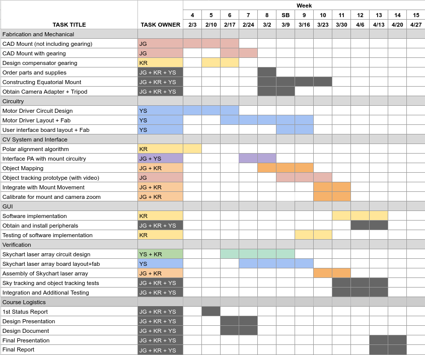
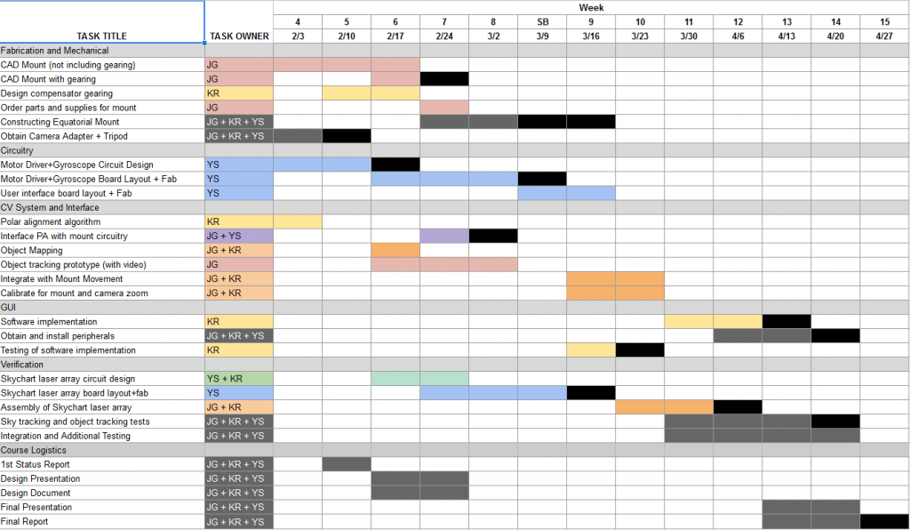
As stated earlier, the completion deadline for the motor controller board has been pushed back a week to allow for the addition of shoot-through protection circuitry. The tasks relating to gyroscope circuit design/layout have been updated to omit all mentions to it, as we’ve decided to purchase a commercial gyroscope from Pololu with a pre-made breakout PCB.

As for the object detection it has been delayed a couple of weeks due to other parts of the project taking  more time than previously envisioned. The changes reflected on the schedule is an overall 2 week delay on the object detection.

The updated Gantt chart is below:

Kenny Ramos’s Report for 3/7/2020

For this week we made sure parts were ordered in hopes that we could start assembly the week after spring break. For the first half of the week we worked on fleshing out the report and budget making sure all part decisions were made. We decided that one of the stepper motor speed reducers we were looking into will probably be affected by shipping delays due to the rising COVID-19 epidemic and one of the backups I chose was for the wrong type of stepper motor so we had to respec the speed reduction ratio to 30:1 for NEMA 17 stepper motor. This means that I had to work on altering the reduction ratio of our compensator gearbox to a 43:2 for an effective ratio of 645:1 which is conveniently closer to our ideal 646:1 ratio than from our previous design although less of the speed reduction is being done with a well fabricated part and more with our own gearbox. For the rest of the week I was in between traveling and testing the polar axis alignment error calculator.

Joy’s Status Update for 2020-03-07

I have talked about fabrication details with my team. We submitted a few orders this week for parts. I do not have a lot to show for the object tracking code. A short video is attached. It’s just an example of tracking with KCF (Kernelized Correlation Filters) on a video of stars.

I am somewhat behind on my tasks. I intended to have gotten further with the code than I did this week. Luckily, I have next week (spring break) to catch up.

I intend to spend next week actually writing code, figuring out how small the images can be downsampled to, calculating velocities of objects, tracking multiple objects, improving the UI for selection of objects, etc. I would also like to start working on tests for the object detection and object tracking. I am nervous about how to translate object tracking velocities to panning and tilting of the actual mount.


Team B1 Report for 02/29/2020

Addressing some of the pressing design oriented feedback received:


Some of the feedback we received dealt with how much fidelity the star mount could simulate actual starlight. To address this we plan to discuss the target of each subsystem test. For one, the star simulating mount does not serve the purpose of simulating actual star-light but rather the movement of stars. Since the capture device is out of scope we plan to specify certain restrictions for how much contrast there should be between an object and the “background” (space) in order to allow for accurate “object identification” (tokenization really). This threshold will be tested with generated offsets of real captures taken with a typical entry level capture device (~$700 DSLR cameras [Canon T7i or Nikon D5600]) with 55mm lenses). However, since this is out of scope our stand works with the assumption that these captures meet these metrics [A badly taken capture, for example a long exposure shot of a sodium street lamp, would not meet this].

The rest of the feedback ran along the lines of too little specification in the design presentation as well as some doubts when it comes to competitive analysis. These will all be reflected in the final draft of our design review.


Risks:

There is a risk that Yuyi won’t be able to work much on the circuitry and layout associated with the test setup this week, as CMU’s ECE Open House is scheduled from Tuesday to Thursday of this week. This could push our schedule back because this will leave Kenny to work individually on the circuit design for the laser drivers/motor drivers composing our project’s test setup. Fortunately, the impact of this is unlikely to jeopardize our project. Work on the CV and physical mount is still progressing and the test setup will not be needed until such is completed. Therefore, a contingency plan isn’t really required for this.


Thus far, we haven’t had a need to make changes to the system’s existing design. However, we intend to push the layout and fabrication of the user interface board of our project to the week of Spring Break. The task will then last until Week 9, when our team will begin integrating the CV with the mount’s motor system. The new Gantt chart is as follows:

Yuyi Shen’s Status Update for Feb. 29 2020

I estimate that I’m 1 week behind on the user interface board design and the layout for the motor controller board. I was also meant to start working on the test setup with Kenny, but he’s been bogged down with the mechanical portion of the project. This isn’t entirely unexpected, as I’ve been gone for almost half the week for a graduate student recruitment event. That, and course logistics have taken up a great deal of time (i.e. preparing for the design review presentation and the design report).

This week, I’ve only managed to setup my layout software with component symbols and footprints in preparation for laying out the motor driver board. Motor driver layout is precarious at best, so I’ve spent most of my time reading up on board design guidelines so that we don’t waste time re-spinning a board. I’ve also compiled a Digikey cart for the driver board: https://www.digikey.com/short/zq07q2 as a price estimate. Disregarding the cost of the PCB, the components for a single unit cost $18.91. This high price point is mainly due to the MOSFET gate drivers and H-bridge FETs, so it’s difficult to ameliorate.

To get back on track next week, I’ll first need to work with my team to get the design report done ASAP. Then, I’ll need to finalize the layout for the motor driver board and 8V power supply in the first half of next week so that we can send the orders out. In the remainder of the week, I’ll work with Kenny on the circuitry and layout for the equatorial mount’s test setup. The layout for the user interface board can be pushed back to Spring Break, since there hasn’t been much progress on the software component of the project.

Kenny Ramos. Status Report 02/29/2020

This week was particularly consumed by other logistic aspects of the class so I was unable to get some other things done. I wanted to finalize some of the simulation stuff to have more concrete numbers and figures for the design review as well as address some of the feedback we got from both our professors and peers and reflect that in our final design review.


Operational things accomplished:


  1. Finalized gearbox while I was unable to get the physical parts printed out this week I should be able to address this on the upcoming Monday class.
  2. Finalized turntable design for “star simulator” mount should be able to decide on final design by next week and get that into fabrication.


For next week the final steps to fabrication should be taken after the design review is finalized. Since our budget will also be finalized by then we hope to order every part necessary by next week as well which will allow us to start assembling after the break.

Another pressing matter is spinning up our software component development. Thankfully most of the setup work was already done in week 6 so we are able to get that done relatively quickly. After week 8 and into week 9 we should be starting on some CV prototypes for our stand, including functional astral object identification and dots(pixels) to real movement conversions.


Some of the risks are mostly due to schedule and some unfortunate asynchronicities in our project. Fabrication and ordering should be done by Spring break in order to account for possible travel plans or previous appointments by members of our team so not meeting that could cause real problems. This means that all of our devotion to this class should be focused on meeting that schedule goal.

Joy’s Status Update for 2020-02-29

I’m two weeks behind. I got sick. I spent some time working on the design report with my teammates. I have started but have nothing to show for the demo. I have not ordered parts. Same “next week tasks” as last week, for the most part:

  • I would like to catch up on ordering parts and getting information about fabrication credits.
  • I would like to start on the object tracking demo. I will be attempting to create a demo for object tracking. I will test it with video samples. Currently, I don’t know what kind of quantitative result would be considered “passing,” but the purpose of this software prototype is to figure out how small the resolution of the images can be before the performance of the object tracking decreases dramatically.
  • I would like to start working on tests for the object detection and object tracking.
  • I would like to finalize fabrication details with my group members and begin with fabrication.

Yuyi Shen’s Status Update for Feb. 22 2020

This week, I wrapped up the circuit design for the motor controller and did the layout for the motor power supply.

Since the majority of the motor controller circuit (up to the H-bridge gate driver ICs) had been simulated in LtSpice, what remained was the design of the chain of logic gates designed to reduce the 4 individual control inputs of the H-bridge gate driver chips to a single PWM pin with an ENABLE input. This was quickly accomplished by finding a logic buffer with delay-equalized complementary outputs (the CD4041UB chip) and a quadruple AND gate for implementing the ENABLE input (SN74HC08).

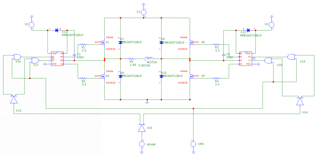
However, I was unable to simulate the full motor controller circuit until very recently, as the PSPICE model I found for the logic buffer was incompatible with LtSpice (the circuit simulator I had been using to work on the motor controller). Luckily, I found that the recently free Micro-cap simulator had functional models for both digital chips, and set up the following testbench for calculating the motor controller’s overall propagation delays:

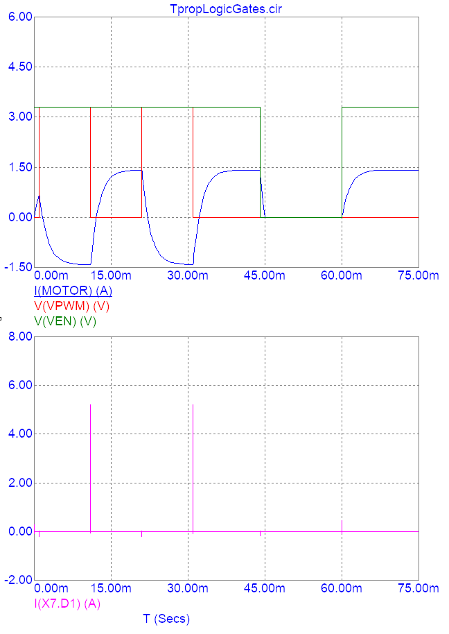
Transient simulation with a handful of rising and falling edges at the PWM and ENABLE inputs produced the following plot:

Using the top set of waveforms, I determined that the PWM input’s rising propagation delay was 1.13 ms, while the falling propagation delay was 1.11 ms. Similarly, I found that the ENABLE input’s rising propagation delay was 1.12 ms, while the falling propagation delay was 0.41 ms. This did not change much when I conducted a worst case analysis with the simulation’s logic delay models. Since these values are consistent with the timing delays I had calculated in LtSpice without the logic gates, there is little reason to doubt the accuracy of the simulation.

Since these delays are insignificant in comparison to the periods with which the equatorial mount stepper motors will be actuated (0.3 sec), we will not have to take them into account when programming the equatorial mount.

Furthermore, I’ve confirmed that the flyback diodes I selected for absorbing voltage spikes at the H-bridge output are adequate. Judging from the lower graph, the most an individual diode will experience is a current spike up to ~5 A, which is substantially lower than the diodes’ non-repetitive peak forward current rating (35 A).

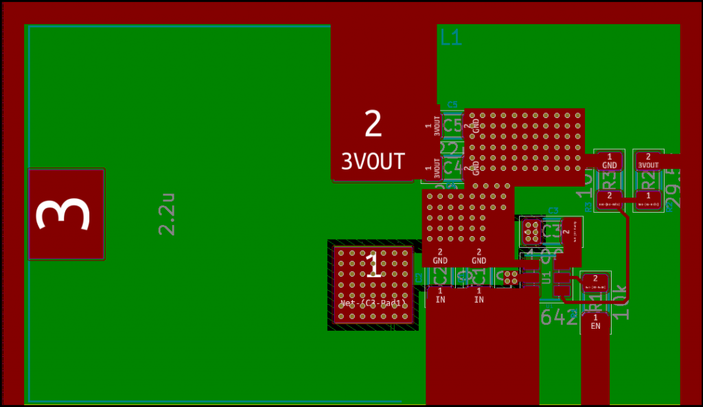
Lastly, I’ve finished laying out a PCB for the stepper motors’ 3V 4A power supplies:

The layout was performed in accordance with the guidelines that were laid out in the buck converter’s datasheet, and no major current-carrying trace has a width lower than 40 mils (the width required for 4A of current to cause a maximum of 10 degrees C of temperature rise with 2 oz. of air-exposed copper). The resulting “standard cell” can be dropped into a standalone instance of PCBnew (KiCad’s layout utility) for integration with the motor controller section. As can be seen, the 3V output is available on 3 sides of the cell for ease of placement in the future. Major current-carrying traces will be exposed to air instead of being covered by solder mask.

Unfortunately, I am behind on my schedule. I have yet to make progress with selecting a gyroscope, which I’ll need to finish up next week after consulting with Kenny on the required precision. Fortunately, this involves minimal circuit design, so catching up will be fairly simple.

Next week, I’ll need to design and layout a 8V buck converter for powering the motor controller ICs, in addition to laying out the actual motor controller in KiCad. This 8V buck converter will be laid out in the same manner as the 3V power supply shown above, although it will be easier to design due to the lower current requirement. Due to this, I do not plan to provide an ENABLE input for it in the layout.

The primary concern at this stage of the design is the layout of the motor controller H-bridges. If there is too much parasitic inductance, there is a possibility that the H-bridge MOSFETs will experience a shoot-through failure condition, destroying them. I plan on including diodes in shunt with the MOSFET gate resistors so that they turn on slower than they turn off (introducing a sort of dead time into the operation of the motor controller). If this fails, I can simply find a motor controller on Digikey that satisfies our requirement.