This week, I worked with Kenny to specify through-hole components suitable for driving the large NEMA-17 motors that were determined to be necessary for implementing the pan and tilt functions of our camera mount (see Team Status Report). Spinning out the PCB that was designed for this task earlier in the semester was found to be infeasible due to the risk of shipping delays impacting our ability to receive the boards from whichever manufacturer we decided to use (the boards would have needed to be manufactured overseas to keep costs low). We examined the possibility of simply ordering the motor drivers that were recommended on the motor supplier’s website (notably the Big Easy Driver on Sparkfun), but found them to be rated for far higher supply voltages than the motors were capable of handling.
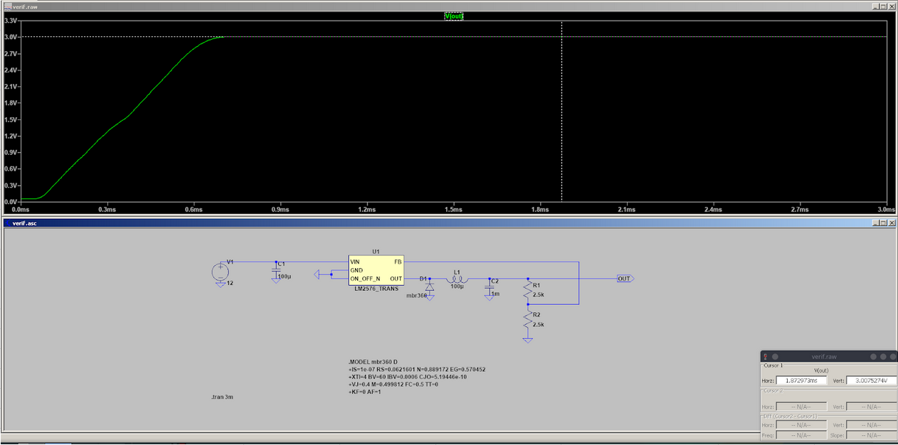
First, we specified through-hole components for a 12V to 3V SMPS for powering the motors. We chose to use a LM2576T-ADJ/NOPB as the SMPS controller, and simply calculated the resistor feedback values for setting the output voltage to 3V. The inductor and capacitor values were kept to the recommended values in the datasheet. LtSpice was used to verify that the design would indeed produce the desired output voltage:
Then, I spec’d out through hole parts for implementing the actual H-bridges for controlling the motors (2 H-bridges per motor). IRFZ24N transistors and IR2302 gate drivers were selected, along with 24.9 Ohm gate resistors so that the driver circuit can tolerate up to 50 nH of parasitic inductance at the MOSFET gates (to reflect the implementation of the circuit on a breadboard). The gate drivers have built-in PWM and ENABLE inputs, so no additional logic was required past a single inverter for buffering the input of the 2nd gate driver. Because the gate driver ICs are synchronous, no special measures were required for generating dead time. High speed 1N4148 diodes were chosen to clamp the inductor voltages to the supply rails.
Verification was carried out in LtSpice:
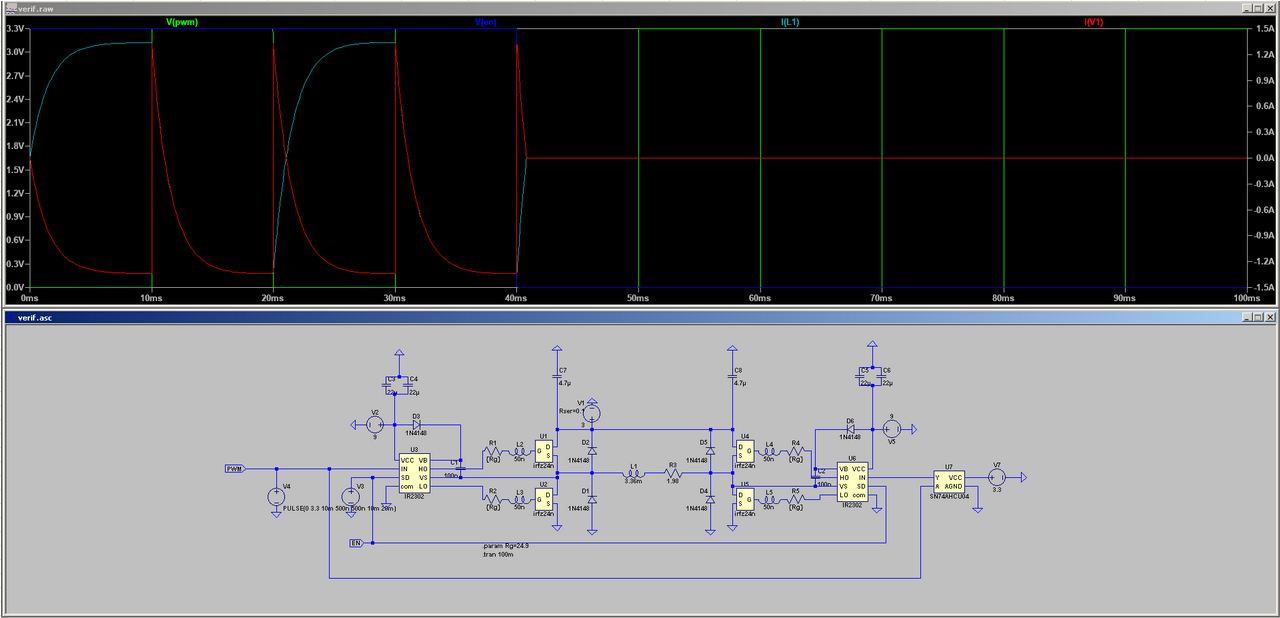
Note that there are no spikes in the I(V1) waveform, indicating that the gate driver ICs are successfully mitigating shoot-through in the MOSFETs. Furthermore, the current through the inductor representing the motor coil falls rapidly to 0 when the ENABLE signal goes low, meaning that this functionality works in simulation.
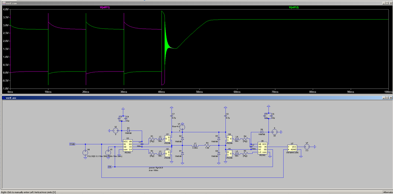
There are voltage spikes at the motor coil during operation, but the flyback diodes successfully keep them within 1 diode drop of the supply rails. There’s also some ringing when the ENABLE signal goes low, but it eventually dies down to a steady-state.
Thus far, I believe I am on track for the 1st demo-in-lab, and the Gantt chart schedule. The first demo will consist of a slide show with simulation results for the motor controllers, and the layout for the motor controller PCB that was designed for the smaller compensator motor. Next week, I will first need to compile the slide show for the demo. Then, I will need to compile a Digikey cart for the final through hole components, and work with Kenny to ensure that we aren’t missing any mechanical components for the test-setup for our mount.