This week, I helped handle a handful of shipping/ordering mishaps. The PCBs that we had originally ordered were somehow mixed up with another team’s order, and Kenny ended up receiving a networking/audio controller board instead of the unipolar motor driver I had designed. Quinn re-ordered the motor controller PCBs, and they should arrive by the 17th.
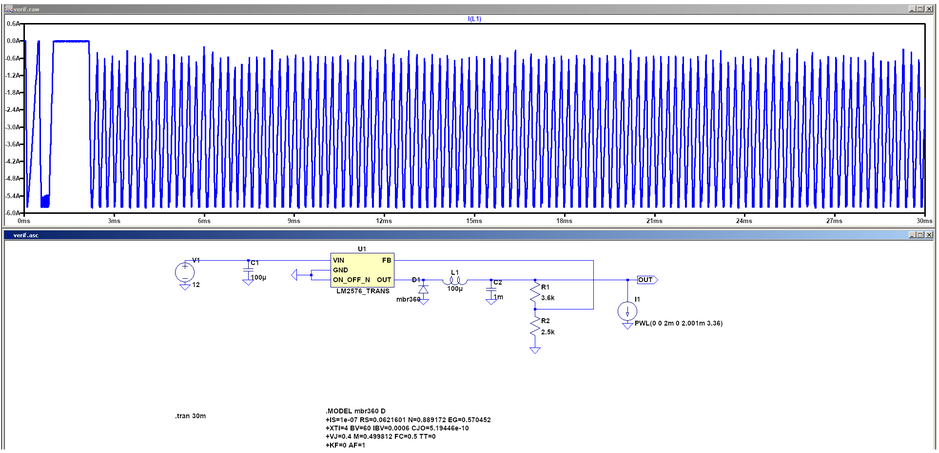
In addition to dealing with the PCB mix-up, I had to revise our Digikey order for the NEMA 17 motor driver parts after reviewing simulation data of the motor driver power supply and the motor driver itself. After extending the transient simulation time for the motor driver power supply, I found that the SMPS’s inductor current oscillated between 0.6 and 6A, with an RMS average of 3.73A:
Since this was far beyond the current rating of the original inductor I’d specified for the SMPS, I asked Joe to cancel the original Digikey order, and changed the Digikey cart to use inductors that were rated for a maximum of 9A RMS. Since this maximum current would result in the maximum survivable temperature rise for the inductor (roughly 60 degrees C assuming the ambient temperature is 25C), I estimated that the newly selected inductor would experience temperatures of roughly 50C in operation. Kenny will need to be careful not to touch the SMPS inductors with his bare hands while the NEMA 17 motors are running, but they will otherwise be 35C below their maximum operating temperature.
Furthermore, a review of the transient currents through the motor driver core’s bootstrap diodes in LtSpice revealed that they experience regular spikes on the order of 1.5A and an inrush current in excess of 2.5A. Since their maximum current spike rating was 2A, I judged this to be potentially hazardous and switched them out for MBR360s, which are rated for 80A spikes. We were already ordering a handful of MBF360s for the motor driver SMPSs, so this wasn’t much of a load on the budget.
Lastly, I checked the power dissipation of the LM2576 regulator that I was planning on using for the motor driver SMPSs in simulation, and found that it would dissipate an average of 11W in steady state operation. Since the thermal resistance of the regulator’s package was specified to be 32.4 C/W, this would have resulted in a temperature rise of about 360 degrees Celsius if we ended up operating it without a heatsink. Obviously, this would have destroyed the device rather quickly. To prevent this, a heatsink with a natural thermal resistance of 3.8C/W was added to the original Digikey cart, in addition to a mounting kit with a mica insulator for the regulator tab. This thermal resistance is slightly less than half of the maximum required thermal resistance to keep the regulator at or below the maximum operating temperature of 125C (9.04 C/W), and should keep the regulator temperature down to 67C.
Lastly, I made sure to put in an order for 3 ULN2803 Darlington transistor arrays as a contingency in case the PCB re-order for the motor controller doesn’t get shipped to Kenny’s house in time for us to make the deadline for the demo.
Thus far, I am on track with my contributions to the project. Next week, I hope to consult with Kenny on the final construction of our camera mount’s electronics, and with Joy on the interface between the Raspberry Pi and the motor controllers.
