Team Status Report for 4-24-21

Over the past week, we have integrated our FPGA camera-to-VGA pipeline with our image processing suite, specifically the chroma-key filter. We have also hooked up all four cameras to the FPGA using an HSMC expansion card. Detailed pictures can be found in Breyden Wood’s status report here. What remains is integrating the fully integrated FPGA with the live studio and pyramid again as well as image enhancement (through specially configuring camera settings and such). Additionally, we need to test the studio and image quality metrics as described in our original proposal and later design report.

We have made some minor modifications of our design to allow the user to tune the background removal algorithm by using the FPGA’s hardware switches. The user can set both the background color that is removed as well as the sensitivity of the background removal, and they can also use a switch to turn the chroma-key filter on or off. This enhances the user experience of using our project and does not incur any monetary costs. The logic units and memory bandwidth costs are also well within the capability of the FPGA.

Our most significant risk at this time is the image quality of the cameras. Some of our cameras have faulty auto-exposure and/or white-balance settings that greatly impact the quality of recorded video. Our mitigation strategy is individually swapping and testing the cameras to make sure the cameras we are using do not have defects that impact our project. Because we bought eight cameras when our project only requires four, we should be able to easily mitigate this risk with our existing cameras. Otherwise, we do have enough remaining budget to buy additional cameras as necessary.

Here is our updated schedule. There are no significant changes. The only changes are final clarifications on our previously ambiguous task assignments at the end of the semester. Our progress is definitively on track as our project is almost complete.

Jullia Tran’s Status Report 04-24-2021

This week, I work with Breyden to integrate Grace’s filter into the pipeline, wiring up the remaining camera and mounting them onto HSMC.

One issue we ran into at first was the filter seems to have an MSB issue. We found out that it was due to the signed extended mechanism was incorrectly implemented. Instead of sign extending the MSB, the LSB was used instead. This was a quick fix and once that was fixed, the chroma keying algorithm works perfectly (some pictures are in Breyden’s blog post).

When we plug in the second camera into GPIO, we noticed there was an issue with the White Balance of the second camera seems to be much better than the first camera. However, they both were using the same settings and outputs generated from the same Arduino Uno. After mounting the third and fourth camera, we realized that the later cameras that were being mounted have a much better White Balance and auto-exposure sensitivity than the first one. We then switched this camera out for a better one and now all the cameras are generating video feeds with similar output. Since our feed back from the interim demo was focusing on the quality of the video, we realized that this might be due to the fact that the first camera seems to be defective, as shown when the video feed quality of the newly mounted cameras were much better than the first one.

To address the issue with our demo’s video quality being low because of streaming through Zoom and also partly because the demo was filmed in the dark, we are planning on using a nicer camera to film the demo and brightening up the scene of our product so that the camera can capture our product better and in a more impressive manner.

Below are images of the a comparison between the first and second camera’s White Balance issue. Note that the better camera captures the yellow hue of the room better, doesn’t make the room looks washed out. Because of this, the image quality seems more crips as compared to the other camera where the exposure and the white balance seems to be set too high.

This image shows the effect of auto-chroma keying. The details about the user-interface built for this feature can be read in Breyden’s post.

Breyden Wood’s Status Report for 4-24-21

These past two weeks I have (with the help of Grace and Jullia) wrapped up all the finishing touches on the FPGA and camera side of our project.

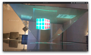
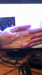
Firstly, I took Grace’s complete chroma key filter and integrated it into the memory-to-display pipeline. Her filter allows us to select any color value in 565 space and remove all pixels matching that value within a user-settable threshold. I integrated this filter into our pipeline along with all 18 hardware switches and LED displays so that the user can easily fine-tune the removed background color and how sensitive the filter should be. Furthermore, to aid in this tuning process, I added two buttons to work as a temporary filter-disable and a “display color to be removed” option. This allows the user to input a value in hex using the switches and LEDs and tweak it by comparing the removed color to the background color until the filter has the desired effect. In my testing, the filter works extremely well and can remove a variety of colors nearly completely (even in the adverse lighting conditions of my room). Sample photos of the filter and hardware-switch UI can be seen below, and we expect the results to be even better in a controlled lighting scenario such as the studio.

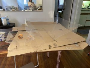
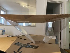
After completing this, I integrated the remaining three cameras to complete our four camera setup (one more on GPIO, two more on the HSMC expansion card). As predicted, this process was fairly straightforward and did not require too much time in Verilog outside of physically wiring the cameras into the board. A photo of this can be seen down below. I also took care of fixing a few image-quality issues that were pointed out to us in our demo feedback (a white bar on the top of the images, and some distortion near the bottom). These fixes were easy to implement (some minor memory errors), and are no longer present in our working product. Thus, essentially all of the FPGA work is done and our project is very near completion. All that remains now is to connect the cameras into the studio, tweak some of the Arduino settings to get an optimally sharp and clear image, and run our image quality tests that we identified earlier in the semester.

As part of the image-enhancing process, I will likely swap out the first connected camera we have been using for one of our spares sometime this week. As noted in the feedback for our demo, the image quality wasn’t the best (and we ran into plenty of issues with auto exposure and auto white balance off-camera). Now that all four cameras are connected, it is clear that the first camera is slightly defective and gives a significantly worse quality image than the other three. This may be due to either an issue in QC (one of the cameras I tested was dead on arrival), or it may be damaged from me accidentally shorting a few of its pins while probing with the oscilloscope a few weeks ago. I plan to quickly make this swap and complete the studio integration this upcoming week so that we are “good to go” for our final presentation and demo!


P.S. The extremely poor image quality here is due to the fact that I am photographing an extremely old VGA panel with my phone. The image looks far better in person and is free of the defects seen in this image (the blue line is from the panel being damaged, and the image distortion is from me having to “pause” the FPGA by unplugging the camera’s power so that I can use my phone to photograph).

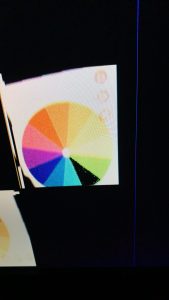
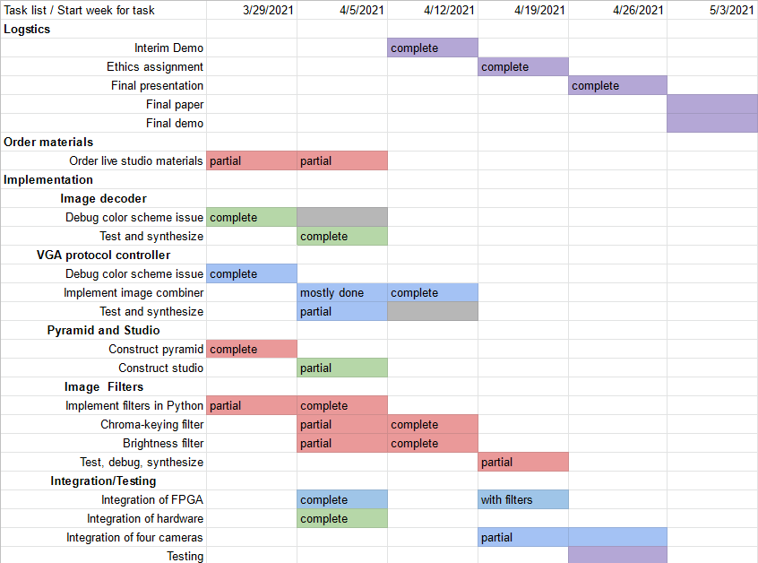
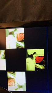
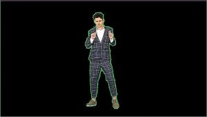
An example of the chroma-key filter in action. The black slice of the color-wheel is a vivid green which the FGPA was configured to remove. As demonstrated here, the filter removes essentially all of the target color while not touching the nearby colors (lime and teal).

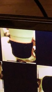
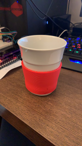
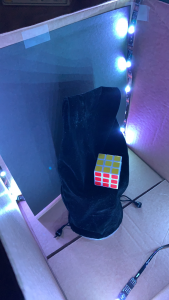
Here, I tested the image removal on a real-world object with texture. The grip on this coffee cup is a vivid red with lots of shadows and ridges that we anticipated making removal hard. Despite this challenging real-world test, Grace’s threshold feature built into her filter was able to detect even the off-red shadows as part of the “intended removal color” and handled it extremely well, removing essentially all of the grip as shown here.

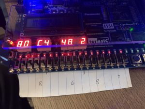
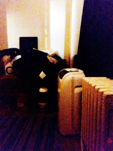
This is a photo of the barebones user interface I constructed to enable real-time configuration of the chroma key settings. Of the 18 hardware switches, we are using 5 for red and blue, 6 for green, and 2 for threshold (matching 565 color and allowing 4 levels of threshold removal). The current settings are displayed on the HEX outputs in RR GG BB T format, and the rightmost button temporarily changes the display to flash the currently set color for easy comparison to the background. The button just to the right of that bypasses the chroma-key filter to allow for a “before and after” comparison to ensure the filter isn’t removing anything desirable.

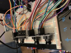
Here is a photo of all four cameras connected and functioning with our FPGA. All four of them work as intended and output independently to the screen as desired for our final product.

Grace An’s Status Report for 4-24-21

Over the past two weeks, I have finished the desired image filters (chroma-key, contrast, and brightness). I wrote a chroma-key implementation in SystemVerilog that takes in two 16-bit pixel values and a threshold determiner and outputs either the original 16-bit pixel value or zero depending on whether the provided pixel value is sufficiently close to the provided “background” pixel value. This implementation also uses Quartus’ synthesized nine-bit multiplier modules on each “color” in the 565 pixel values. The specified background color and threshold values also allow the chroma-keying module to work with the FPGA hardware switches such that the removed color and the sensitivity of the chroma-key filter can be set dynamically after hardware configuration. I have also finished contrast and brightness modules, although that would be tested at a later date (when the entire studio is integrated with all four cameras and the FPGA). It is likely that the contrast module would require using decimal multipliers on the FPGA.

As Breyden has the FPGA and cameras in his possession, he very kindly tested and debugged my code (which had an LSB and MSB mix-up error) and improved the threshold handling to be more sensitive across the desired background ranges. The effect of our image filtering modules can be seen in his status report this week.

I am on track with the schedule as all image filters are more or less finished. Over the next week, I will work on the final presentation and the final report as we finish up our project. I may also help Breyden with the integration process and/or the testing process depending on logistical details.

Grace An’s Status Report for 4-10-21

Over the past week, I have continued to purchase items needed for the live studio, including additional colors of construction paper (in order to experiment with chroma-keying with different background colors), a VGA-to-HDMI converter (to connect the FPGA output to the TV), and additional OV7670 cameras (in case any get damaged during the integration process).

Throughout the week, I continued to research de-noising filters that could be implemented on an FPGA, such as a median or low-pass filter. Unfortunately, both of these filters require operating at multiple pixels at a time, which is extremely difficult alongside the memory constraint. Fortunately, as mentioned in the Team Status Report this week here, we do not need a de-noising filter because the live studio’s lighting is sufficiently bright as to render chromatic noise largely nonexistent.

In addition to finishing software implementations of chroma-keying and brightness and contrast filters, I have also written hardware descriptions (in SystemVerilog) of modules that support chroma-keying and brightness and contrast filters. Given Breyden’s suggestion about the FPGA’s hardware switches, I have designed these modules to flexibly take in different values of input.

My progress is on schedule, thanks to Jullia kindly taking over the task of constructing the live studio. Over the next week, I will fully test, debug, and synthesize implementations of chroma-key and brightness and contrast filters. I may also assist with creating a cardboard top over the pyramid that is more professional and appealing than the existing one. Aside from that, I will assist with the final testing and integration that represents our last weeks of capstone.

Team Status Report for 4-10-21

This week, Jullia constructed the live studio, and Breyden worked further on the image decoder. Most importantly, we have integrated our separate subsystems (pyramid, FPGA, live studio, and TV) together in preparation for the interim demo. A video of our working system can be found here and further images of the working system can be found in Jullia Tran’s status report here.

Excitingly, we found that one of our risk mitigation strategies with chromatic noise worked very effectively. The bright lighting of LED lights in our live studio was extremely effective in getting rid of chromatic noise in the output from the OV7670 cameras. In light of this development, we do not plan to add a denoising filter to our image processing suite. This is particularly beneficial because we have also elected not to do image convolution due to memory bandwidth problems.

As the majority of our project has been integrated at this point, most of our significant risks (chromatic noise, issues in integrating OV7670 cameras with the FPGA, etc.) have already been mitigated. Our remaining risks largely constitute our memory bandwidth, remaining quantitative tests, camera autoexposure settings, and the image filters. In order to mitigate these risks, we will test our image filters in simulation and also when synthesized (as well as in a higher-level programming language), and we will also experiment with the camera settings and Quartus to finalize details.

As usual, our updated schedule is below. The only difference between the last week is that Jullia constructed the live studio instead of Grace. Everything was still accomplished with the appropriate timing. After the interim demo, the plan is to finish and perfect our project: integrate all cameras, engage in quantitative testing, add image filters, experiment with different background colors, and build and/or buy a better platform for objects in the live studio.

Jullia Tran’s Status Report for 4-10-21

This week, I constructed the live studio using cardboard, tape and construction paper. The inner walls is covered with black construction paper. I also strung LED lights around the corners of the walls to create uniform lighting on the object. Currently, we have a plastic cup for the platform but we are planning on improving this for our final design. The black construction paper ended up not quite being black through the camera due to the lighting of the LEDs and they showed up black. Because of this, we ended up covering the platform and some of the background with black velvet to create a black background that won’t show up on the camera, mimicking the effect of the chroma-key filters. Currently the live studio only have 1 camera installed. However, we are able to test out the full pipeline, from camera inside the studio to FPGA to the TV onto the pyramid. The full design on the FPGA is ready with all the memory blocks created; we just haven’t wire up all the cameras.

Breyden helped with putting the entire set up together. We then adjust the White Balance once we have the entire set up. We also spent some time to film some sample clips for our interim demo. I then stitched up the video and it can be seen through this link here.

We thought that overall, the hologram effect looks quite decent and the floating effect was achieved. The quality of our filming could be improved because this small film was filmed using an iPhone camera in low lighting. We were thinking for final demo, we can maybe film in slightly brighter settings because the illusions seems to still hold in brighter settings.

Below are images of the live studio and of the hologram under bright light studio.

Breyden Wood’s Status Report for 4-10-21

This week, we were able to finish up all the work we were planning for the interim demo and are near to the “MVP” we defined for our project. I was able to take one camera and feed it into all four memory banks (which I created this week) at a resolution of 240p per camera with a total output resolution of 720p (this is the final memory hierarchy are planning to use for our project). From there, I was able to finalize the white balance of the camera and integrate the entire setup into the studio we constructed. This was combined with the TV and the pyramid into a fully functional studio-to-FPGA-to-display pipeline which we used to display some sample objects for our interim demo. This integration went smoothly and we were able to capture footage for our demo video of our complete pipeline. Our progress is on schedule, as all we have left to do is connect the other four cameras (all the FPGA design is set up for this, they are just not physically plugged in) and add the background removal filter for our final project. This next week I hope to continue working on adding the other cameras to the FPGA and working out some kinks in the autoexposure settings of the cameras, as it was a bit unpredictable in the filming of our demo video. My progress this week can be seen in the demo video of the project.

Jullia Tran’s Status Report for 4-3-21

This week, Breyden and I have been working on the camera issue with the color input of the camera reading incorrectly on the FPGA. This bug was a major hinder to achieving our MVP. In order to better debug this issue, we acquired an oscilloscope from the ECE labs to check out the inputs and outputs provided by the camera and the FPGA. Immediately by checking the input from the camera, we realized that the outputs were at 2.6V while the FPGA was reading these inputs at 2.5V. Since the voltages were too close to the threshold, the FPGA was misreading some inputs as low instead of high because sometimes the camera would output some high inputs as slightly lower than 2.5V. We fixed this issue by adjusting the default FPGA high input threshold to a lower threshold: 1.5V.

The next bug we encountered was our design was reading at negedge instead of posedge because a lot of the forums online suggested that the negedge of the camera produced more accurate results. This turned out to not be the case and the result can be seen clearly on the oscilloscope. We fixed this by just reading on a posedge instead of negedge and the noise in the image reduced.

The third bug we encountered was with the SCCB protocol. We thought that the arduino was communicating well with the camera because when we change some of the settings of the arduino, the resulting image seems to change. However since we weren’t able to get the correct image output on the VGA, we thought it was just our decoder not reading data correctly. After looking at the oscilloscope, we realized we were using a clock that is too high for this protocol, at 475kHz, which is higher than the max clock frequency of the camera’s SCCB (400kHz). We changed this frequency and we were able to get the correct image out displayed on the monitor. We were also able to change bit pattern, white balance, and some other camera settings to modify some of the color settings.

We now have a working color inputs and correctly reading these inputs to be displayed onto a monitor.

Below are some of the output images we got. Some of the noise seen here are resulted from the low-light of the room. The noise is reduced as better lighting is in the room.

Grace An’s Status Report for 4-3-21

This week, I worked on constructing the final full-size model of the holographic pyramid, which is currently at the level of detail needed for the MVP and interim demo, although we will make changes to make it clearer and more visibly professional for the final presentation.

One unexpected issue was that unlike the smaller prototypes, the full-size model’s walls sagged slightly at the center of the edges, which distorts images reflected off of the sides. Thanks to Jullia’s excellent suggestion, I cut out and taped a cardboard square above the pyramid, which adequately straightens the sides of the pyramid. This cardboard top also has the benefit of dimming the light immediately under the pyramid, which will improve the visibility of reflected images. For our final model, we will improve our pyramid by painting the cardboard black.


Figure 1: The holographic pyramid adjacent to its 1:2-size model. Despite the 1:2 size model’s perfect proportions, the full-size model’s walls sag slightly, especially in the center.
Figure 2: The holographic pyramid with a cardboard top. By virtue of being taped to the cardboard square, the pyramid’s sides sag significantly less.

Also during this week, I also implemented our desired image filters (chroma-keying, brightness, and sharpness) in Python. This enables customization of constants (such as the aggressiveness of the background removal, increase in brightness, etc.) and testing out the filters on the camera images before implementation in hardware. An example of the filters (not using output from the OV7670 cameras) is shown below:

Figure 1: The original test image
Figure 2: The test image through chroma-keying, brightness, and sharpening filters. The chroma-keying software implementation was hard-coded to remove the specific background color in the image.

I am on track with the updated schedule, in which software implementations of the image filters was moved to this past week, and the live studio construction was moved to next week. Over the next week, I will construct the live studio, possibly with Jullia’s assistance (depending on how busy she is with further hardware implementations). Additionally, I will also finish up the software implementations of the image filters by running them on images captured from our OV7670 cameras. I will also research and implement simple algorithms for noise removal in software to work with the OV7670’s chromatic noise, such as by using a low pass or median filter. It is likely that our sharpening filter may be replaced with a noise removal filter instead, although our final design may include both.