Jullia Tran’s Status Report 5-8-21

This week, I spent the beginning of the week working on the final presentation demo and going over what Breyden was going to say for the final presentation. I worked on editing the Gantt chart to reflect our changes, and also edit some of the slides to make it more readable through the use of tables, cutting back texts, and adding more visual diagrams.

Later this week, I worked on recording some parts of the video for the final demo presentation. My part is to talk about the studio development, the design choices we made, and the final design that we have for the studio. I also worked on editing our final demo and putting together the final video. I need to go over the footages that we recorded from last week, along with some more footages we got from this week and find a way to best put together a video that would represent and displayed our project in the nicest way so that it’s easy to showcase our final product. Each member of the team recorded an audio recording, and an audio recording with the slides presentation to better explain the project’s work flow, and the final product. We also have B-roll shots of our working products from multiple angles, objects, and object interactions that needed to be put together.

We also work on putting together the poster presentation that is needed for Monday night.

Jullia Tran’s Status Report 5-01-2021

This week, our team gathers at my place to work on the project together. We work on integrating the entire pipeline together, from the output of the camera onto the display. Breyden and I first worked together to set up the TV and the pyramid because it’s a 55-inch TV so this set up task requires 2 persons.

I work on parts of adjusting the studio to make it works with 4 cameras. As mentioned in the team’s status report, we ran into wire length constrained and because of this, we decided to put the FPGA inside our studio. For this, I cut out a platform and place it on top of the FPGA. I also work on cutting up the felts to cover the walls. The dimension of these felts has to be so that it doesn’t cover up the LEDs running along the side of the studio. We also tried multiple colors felt and so all these sheets of felts need to be cut out. In each of the felt, there needs to be a hole so that the camera lens can fit through. There are 4 different colors that we tried (black, blue, light green, dark green) and each of these need 5 sheets of felt, 4 for the walls, and 1 for the bottom. Grace also helped me with cutting these felt. After cutting, we need to insert it into the studio and this tasks was also done with multiple iterations because we didn’t realized at first that we don’t want the felt to fully cover the LEDs lights because this turns out that the light becomes too diffused, hence some adjustment is needed.

I also work on cutting some of the holes in the studio so that wires can go through, as well as holes for the 4 cameras and their wires. This is done by directly cutting into the studio and measuring the height so that the placement of the cameras would be somewhat in the same leveling plane.

The lighting of the studio also needed to be adjusted. I helped with cutting strips of felt to diffuse specific light on the LEDs strip. Multiple iterations of this task need to be done since we need to figure out which configurations would best depict the video feed the best.

When we film some of the shots, I also help with some of the set up, clearing out space for the camera, and being Breyden’s assistance for whatever he needs to film. I also provided some feedbacks for some of the shots we might want to do for filming. I also help with documenting some of our progress with pictures as we work on this project.

I printed out the MTF test so that we can do testing with the setup. This test tests the distortion of the pyramid and since we have the MTF testing card printed out, we were able to just run this test.

We are on track with our tasks. We just have to finish up testings and put together the video, which is what I will be doing in the next week.

Team’s Status Report 5-1-2021

At the beginning of the week, we worked together on the final presentation slides.

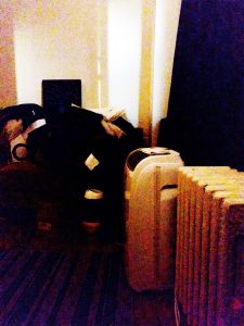
Later this week, we worked on integrating the studio with 4 cameras and outputting to the TV, on which the pyramid sits. We came together as a team to work on this at Jullia’s house. We spent some time mounting the four cameras to the side of the studio. Because longer wires have more electrical noise, and our cameras are especially sensitive to electrical noise, the wires must be short as possible. To ensure this, we placed our FPGA and the Arduino inside the studio at the bottom, and added a cardboard platform on top where our object can be placed on. We also spent some time cutting out some holes in the studio so that we can have access to the switches of the FPGAs. This allows us to adjust chroma keying color, discussed later in this status report. These changes to the design improve our project and do not affect its cost.

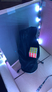
Also, we spent the bulk of our time adjusting the white balance, auto-exposure of cameras and lighting of the studio to have each panel of the pyramid output to be similar enough to each other. This is done by switching out a couple cameras because their sensitivities have slight variation. We also experimented with the lighting between the LEDs along the side of the walls vs point lighting. We found that point lighting creates gradient of shadows, especially when interacting with the object. These shadows make the background extremely difficult to remove, so point lighting is not desirable for our project.

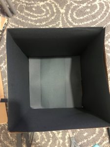
Furthermore, we also spent signficant time adjusting our chroma key to find the optimal background color. We experimented with multiple colors of felt along the wall and the colors of the platform. We tried dark green, light green, blue and black and experimented between them to have chroma key close to removing all of the background. We prepared multiple felt sheets with specific dimensions that will fit into the studio, and then adjusted the chroma key to match the color that shows up on the camera inside the studio, where lighting is also introduced. The lighting was adjusted by dimming the overall studio, and dimming or diffusing specific light on the LEDs strip.

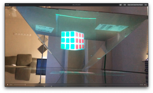
We also started testing our HoloPyramid. The latency between display and real time action turns out to be around 22ms of delay which significantly surpasses our initial requirement of 250ms of delay. This latency is more than low enough to be imperceptible to the human eye, and confirms that  human eyes perceive the visual display as real time.

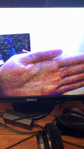
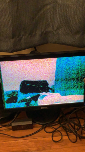
Our most significant risk is that the camera exposure does not have a lot of dynamic range. When we have a bright object against darker backgrounds, the camera struggles to auto-expose. This causes the object to be shown with the incorrect exposure. To mitigate this risk, we used brighter backgrounds and experimented with lighting. Another risk we have is that the wires are very sensitive and the connectivity is not the greatest between the camera and the GPIOs pins. When the wires get loose, noise becomes apparent on the output which decreases our video feed quality. To mitigate this risk, when noise occurs, we go into the bottom of the studio, where the FPGA lives and adjust the wire connections using tweezer to make them tighter.

We also started working on trying to film for the final demos, capturing footage of our current project.

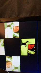
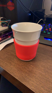
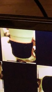
Images of our project can be found in this link (we ran out of space for our website).

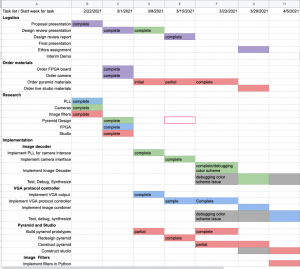
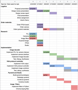
Our Gantt chart can be seen here. Our schedule has not changed; however, some additional tasks were added to the end to reflect our current integration and testing projects with greater granularity and details.

Jullia Tran’s Status Report 04-24-2021

This week, I work with Breyden to integrate Grace’s filter into the pipeline, wiring up the remaining camera and mounting them onto HSMC.

One issue we ran into at first was the filter seems to have an MSB issue. We found out that it was due to the signed extended mechanism was incorrectly implemented. Instead of sign extending the MSB, the LSB was used instead. This was a quick fix and once that was fixed, the chroma keying algorithm works perfectly (some pictures are in Breyden’s blog post).

When we plug in the second camera into GPIO, we noticed there was an issue with the White Balance of the second camera seems to be much better than the first camera. However, they both were using the same settings and outputs generated from the same Arduino Uno. After mounting the third and fourth camera, we realized that the later cameras that were being mounted have a much better White Balance and auto-exposure sensitivity than the first one. We then switched this camera out for a better one and now all the cameras are generating video feeds with similar output. Since our feed back from the interim demo was focusing on the quality of the video, we realized that this might be due to the fact that the first camera seems to be defective, as shown when the video feed quality of the newly mounted cameras were much better than the first one.

To address the issue with our demo’s video quality being low because of streaming through Zoom and also partly because the demo was filmed in the dark, we are planning on using a nicer camera to film the demo and brightening up the scene of our product so that the camera can capture our product better and in a more impressive manner.

Below are images of the a comparison between the first and second camera’s White Balance issue. Note that the better camera captures the yellow hue of the room better, doesn’t make the room looks washed out. Because of this, the image quality seems more crips as compared to the other camera where the exposure and the white balance seems to be set too high.

This image shows the effect of auto-chroma keying. The details about the user-interface built for this feature can be read in Breyden’s post.

Jullia Tran’s Status Report for 4-10-21

This week, I constructed the live studio using cardboard, tape and construction paper. The inner walls is covered with black construction paper. I also strung LED lights around the corners of the walls to create uniform lighting on the object. Currently, we have a plastic cup for the platform but we are planning on improving this for our final design. The black construction paper ended up not quite being black through the camera due to the lighting of the LEDs and they showed up black. Because of this, we ended up covering the platform and some of the background with black velvet to create a black background that won’t show up on the camera, mimicking the effect of the chroma-key filters. Currently the live studio only have 1 camera installed. However, we are able to test out the full pipeline, from camera inside the studio to FPGA to the TV onto the pyramid. The full design on the FPGA is ready with all the memory blocks created; we just haven’t wire up all the cameras.

Breyden helped with putting the entire set up together. We then adjust the White Balance once we have the entire set up. We also spent some time to film some sample clips for our interim demo. I then stitched up the video and it can be seen through this link here.

We thought that overall, the hologram effect looks quite decent and the floating effect was achieved. The quality of our filming could be improved because this small film was filmed using an iPhone camera in low lighting. We were thinking for final demo, we can maybe film in slightly brighter settings because the illusions seems to still hold in brighter settings.

Below are images of the live studio and of the hologram under bright light studio.

Jullia Tran’s Status Report for 4-3-21

This week, Breyden and I have been working on the camera issue with the color input of the camera reading incorrectly on the FPGA. This bug was a major hinder to achieving our MVP. In order to better debug this issue, we acquired an oscilloscope from the ECE labs to check out the inputs and outputs provided by the camera and the FPGA. Immediately by checking the input from the camera, we realized that the outputs were at 2.6V while the FPGA was reading these inputs at 2.5V. Since the voltages were too close to the threshold, the FPGA was misreading some inputs as low instead of high because sometimes the camera would output some high inputs as slightly lower than 2.5V. We fixed this issue by adjusting the default FPGA high input threshold to a lower threshold: 1.5V.

The next bug we encountered was our design was reading at negedge instead of posedge because a lot of the forums online suggested that the negedge of the camera produced more accurate results. This turned out to not be the case and the result can be seen clearly on the oscilloscope. We fixed this by just reading on a posedge instead of negedge and the noise in the image reduced.

The third bug we encountered was with the SCCB protocol. We thought that the arduino was communicating well with the camera because when we change some of the settings of the arduino, the resulting image seems to change. However since we weren’t able to get the correct image output on the VGA, we thought it was just our decoder not reading data correctly. After looking at the oscilloscope, we realized we were using a clock that is too high for this protocol, at 475kHz, which is higher than the max clock frequency of the camera’s SCCB (400kHz). We changed this frequency and we were able to get the correct image out displayed on the monitor. We were also able to change bit pattern, white balance, and some other camera settings to modify some of the color settings.

We now have a working color inputs and correctly reading these inputs to be displayed onto a monitor.

Below are some of the output images we got. Some of the noise seen here are resulted from the low-light of the room. The noise is reduced as better lighting is in the room.

Team Status Report for 3-27-21

Last week, our team spent the majority of the time working on the design report.

This week, our team spent time working on two major parts: getting data from the camera and outputting it into the VGA display, and the construction of the pyramid. We were able to get outputs from the camera and show it on the monitor. However, we ran into an unexpected, significant risk: the color scheme of the output. More details about this can be found in Breyden’s and Jullia’s status report here and here. This risk jeopardizes significant aspects of our project, including the final product as well as the interim construction of the live studio and chroma-keying implementation. We are managed this risk by highly prioritizing the color scheme until it is fixed, and we also have the backup plan that we planned to use in the case of non-functional chroma-keying: using a black backdrop and not including a chroma-keying implementation. This would enable a working, final project even in monochrome.

Even with the color scheme issue, we were still able to accomplish a lot of the tasks we set out to accomplish for this week: Getting I2c communication protocol to work on the Arduino to set up camera settings, decoding the pixel data coming from the camera, storing it into a frame buffer in BRAM, reading this data out from the frame buffer, and finally outputting it into the VGA display. Since these parts are working, it also shows that our PLLs are working and our design are holding up even with multiple clock domains. This shows the overall pipeline needed for our MVP and so once the color scheme settings issue is fixed, we will have a fully functioning pipeline for the display.

The second task of constructing the pyramid was worked on by Grace. She successfully tested the new plexiglass type which was easier to work with, met our project requirements, and held its shape well when the panels are put together.

Some changes to our design have also increased usage of our budget. Namely, we needed to switch plexiglass types due to the earlier kind not working, which caused us to purchase 24″x36″x0.03″ PET sheets for $34.99 and other different kinds of acrylic sheets for approximately $50 in total.  We also need to purchase different kinds of backdrops for the live studio, in the case of non-functional color, which represents an additional cost. We will mitigate these costs by buying cheaper and fewer items until we are absolutely certain of our final design, though our budget is currently sufficient to manage all of these costs.

The previously mentioned tasks represents our critical path, or the tasks most important for us to achieve our MVP, and we are on track on building our MVP for the interim demo. Below is the updated schedule for this week, showing the tasks we have accomplished and currently working on.

Jullia Tran’s Status Report for 3-27-21

Last week, I spent my time writing the Design Report. I spent time on writing specifically the Architecture Overview, Design Trade Studies, Pyramid Materials and Pyramid Design. I also spent time on writing parts of other sections.

For this week, I spent time writing the image decoder, two sccb modules for FPGA, and a top module that wire these modules together. I then met up with Breyden to debug the full pipeline so that we have the flow of data from the FPGA going out into the VGA monitor. When we were debugging together, we realized that the i2c protocols using the FPGA wasn’t quite working correctly. This could be due to a number of things noise from the wiring connections. After debugging for a while, we decided that it might be easier to use the I2c protocol directly from the Arduino Uno because this was easier to debug. Breyden then took over and debugged some more after this when the issue becomes the color settings of the camera doesn’t quite follow what we expected from the specs sheet after we have set the settings to output RGB. We also worked out together how to instantiate the BRAM and interfacing with this type of memory from the FPGA. We now have a BRAM 2-port buffer that we read and write into so that we can output this data into the VGA monitor. However, we are currently facing the issue of the color not quite being as accurate as it should be: we have RGB565 settings for the camera and decoding in this scheme but the frame seems to be black and white. We are currently trying to handle this and hopefully will have it for next week. As of the progress, even with this issue we are facing, we are still on track because we have accomplished some of the tasks needed to be done for later along with debugging and testing.

Team Status Report for 3-13-21

This week, our team started working on the implementation of our solution approach. The first task was to make sure we are able to generate clocks of different time domain for the VGA display and the camera input. We were able to accomplish this successfully with generating both the ” 640×480@60Hz with a PLL-generated pixel clock of 25.175MHz” for the VGA display and also the 720p60Hz-75MHz clock for the camera. For the camera we were also able to generate a clock of 106.47MHz. This is higher than what we needed but this would mean that we would be able to generate a clock that would support up to 1440×900@60Hz. Breyden was also able to successfully output a test image with the VGA output by controlling the FPGA. Grace was also able to prototype the pyramid construction. She picked up the material from Home Depot and started on the process of constructing the pyramid. She worked on cutting the smaller dimension pyramid, as to test the plexiglass material, construction process, as well as the dimension of the pyramid. One issue, however, is that after prototyping, we realized the material didn’t live up to what we have expected. This will need to be revised in the up coming week. However, the prototype has still been completed and the dimension has been.

These tasks above represents our critical path, which include some of the tasks most important for us to achieve our MVP: Because we have been able to successfully implemented some of the tasks above, our risk involving the PLLs not being able to generate fast enough clock has been mitigated. Below is also the updated schedule that is revised by pushing back everything a week. We are still on track, however, with implementing the MVP. The schedule below reflects the completion of the tasks mentioned above.


Jullia Tran’s Status Report for 3-13-21

At the beginning of this week, I worked on the design presentation. I practiced and record myself a couple times on Zoom to familiarize myself with the presentation mode while presenting.

Later this week, I was handling some of the parts we ordered such as the OV7670 that we ordered and picked up the FPGA from the drop off place. I then arranged with Breyden a time to drop those off for him. I researched about how PLL would work on the FPGA, specifically how it is set in Quartus. Then I worked with the help of Breyden to figure out how the PLL would work with the camera. We were able to set the PLL to generate an output that would support the OV7670 at 720p, 60HZ, which should be around a 75 MHz clock. However, we were able to set the clock to even higher – 106.47MHz. This would support 1440×900@60Hz.

We are quite on schedule. Looking ahead, I hope to have the camera output an image to the VGA controller and showing that on the display.