This week, Breyden and I have been working on the camera issue with the color input of the camera reading incorrectly on the FPGA. This bug was a major hinder to achieving our MVP. In order to better debug this issue, we acquired an oscilloscope from the ECE labs to check out the inputs and outputs provided by the camera and the FPGA. Immediately by checking the input from the camera, we realized that the outputs were at 2.6V while the FPGA was reading these inputs at 2.5V. Since the voltages were too close to the threshold, the FPGA was misreading some inputs as low instead of high because sometimes the camera would output some high inputs as slightly lower than 2.5V. We fixed this issue by adjusting the default FPGA high input threshold to a lower threshold: 1.5V.
The next bug we encountered was our design was reading at negedge instead of posedge because a lot of the forums online suggested that the negedge of the camera produced more accurate results. This turned out to not be the case and the result can be seen clearly on the oscilloscope. We fixed this by just reading on a posedge instead of negedge and the noise in the image reduced.
The third bug we encountered was with the SCCB protocol. We thought that the arduino was communicating well with the camera because when we change some of the settings of the arduino, the resulting image seems to change. However since we weren’t able to get the correct image output on the VGA, we thought it was just our decoder not reading data correctly. After looking at the oscilloscope, we realized we were using a clock that is too high for this protocol, at 475kHz, which is higher than the max clock frequency of the camera’s SCCB (400kHz). We changed this frequency and we were able to get the correct image out displayed on the monitor. We were also able to change bit pattern, white balance, and some other camera settings to modify some of the color settings.
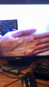
We now have a working color inputs and correctly reading these inputs to be displayed onto a monitor.
Below are some of the output images we got. Some of the noise seen here are resulted from the low-light of the room. The noise is reduced as better lighting is in the room.