Team Status Report for 3-27-21

Last week, our team spent the majority of the time working on the design report.

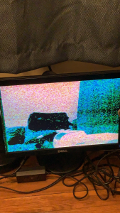
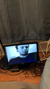
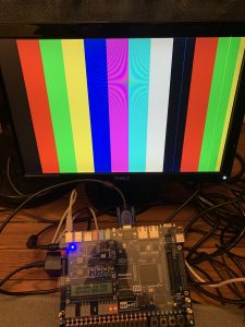
This week, our team spent time working on two major parts: getting data from the camera and outputting it into the VGA display, and the construction of the pyramid. We were able to get outputs from the camera and show it on the monitor. However, we ran into an unexpected, significant risk: the color scheme of the output. More details about this can be found in Breyden’s and Jullia’s status report here and here. This risk jeopardizes significant aspects of our project, including the final product as well as the interim construction of the live studio and chroma-keying implementation. We are managed this risk by highly prioritizing the color scheme until it is fixed, and we also have the backup plan that we planned to use in the case of non-functional chroma-keying: using a black backdrop and not including a chroma-keying implementation. This would enable a working, final project even in monochrome.

Even with the color scheme issue, we were still able to accomplish a lot of the tasks we set out to accomplish for this week: Getting I2c communication protocol to work on the Arduino to set up camera settings, decoding the pixel data coming from the camera, storing it into a frame buffer in BRAM, reading this data out from the frame buffer, and finally outputting it into the VGA display. Since these parts are working, it also shows that our PLLs are working and our design are holding up even with multiple clock domains. This shows the overall pipeline needed for our MVP and so once the color scheme settings issue is fixed, we will have a fully functioning pipeline for the display.

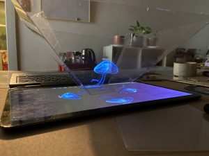
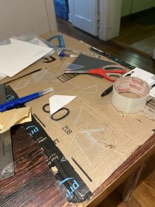
The second task of constructing the pyramid was worked on by Grace. She successfully tested the new plexiglass type which was easier to work with, met our project requirements, and held its shape well when the panels are put together.

Some changes to our design have also increased usage of our budget. Namely, we needed to switch plexiglass types due to the earlier kind not working, which caused us to purchase 24″x36″x0.03″ PET sheets for $34.99 and other different kinds of acrylic sheets for approximately $50 in total.  We also need to purchase different kinds of backdrops for the live studio, in the case of non-functional color, which represents an additional cost. We will mitigate these costs by buying cheaper and fewer items until we are absolutely certain of our final design, though our budget is currently sufficient to manage all of these costs.

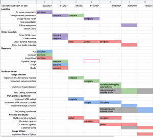
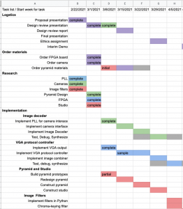
The previously mentioned tasks represents our critical path, or the tasks most important for us to achieve our MVP, and we are on track on building our MVP for the interim demo. Below is the updated schedule for this week, showing the tasks we have accomplished and currently working on.

Grace An’s Status Report for 3-27-21

Two weeks ago, I spent most of my time on the Design Review Report, specifically writing up sections such as the Arduino and FPGA sections of the architecture overview, design trade studies comparing alternate FPGAs and analog cameras for our project, and the budget and work distribution. I also helped revise the final paper, improving conciseness.

Throughout the past week, I have found that nearby stores (Home Depot, Hobby Lobby, Lowe’s, etc.) do not have the size nor optical qualities of plexiglass that we desire, so I ordered acrylic sheets online. Because online shopping precludes the ability to verify the quality in-person, I ordered a variety of plexiglass sheets to see which provides the best properties. Due to shipping times, not all these materials have arrived, and I only received three 24″x36″x0.03″ PET sheets very late this week. Using these sheets, scissors, and masking tape, I have been able to make the 1:2 model shown below:

Figure 1: Over a pre-baked video, the 1:2 prototype displays a satisfyingly convincing three dimensional illusion.

From this 1:2 model, I have found that these PET sheets are finally reflective enough to make a holographic illusion. The 0.03″ thickness is also thin enough to be cut with scissors, which is much easier than with a plastic cutter (although not more precise) and is also sturdy enough the 1:2 model holds together well. There is a very slight (but still noticeable) doubled reflection that presents a concern, and we may want to consider a better attachment method (e.g. optical tape or acrylic glue) to make the final product more professional.

I am running very slightly behind schedule in that I have not completed the entire pyramid yet, since these materials arrived only today. However, I am certain to complete this task early next week, since the 1:2 model was surprisingly easy to construct. I will also investigate methods to improve the reflective quality of the pyramid, such as by using optical tape, suppressing doubled reflections, and/or polishing the plexiglass.

A greater concern is whether the live studio is able to be constructed over the next week, as this requires both materials and verification of the cameras’ field of vision and color capability, and there have been persistent issues with shipping times and the OV7670 cameras. I will definitely order the necessary materials (studio lights, backdrop, etc.) over the next week, but it is possible that I may switch over to preemptively working on image processing, in which case that will be the additional deliverable I will work on over the next week.

Jullia Tran’s Status Report for 3-27-21

Last week, I spent my time writing the Design Report. I spent time on writing specifically the Architecture Overview, Design Trade Studies, Pyramid Materials and Pyramid Design. I also spent time on writing parts of other sections.

For this week, I spent time writing the image decoder, two sccb modules for FPGA, and a top module that wire these modules together. I then met up with Breyden to debug the full pipeline so that we have the flow of data from the FPGA going out into the VGA monitor. When we were debugging together, we realized that the i2c protocols using the FPGA wasn’t quite working correctly. This could be due to a number of things noise from the wiring connections. After debugging for a while, we decided that it might be easier to use the I2c protocol directly from the Arduino Uno because this was easier to debug. Breyden then took over and debugged some more after this when the issue becomes the color settings of the camera doesn’t quite follow what we expected from the specs sheet after we have set the settings to output RGB. We also worked out together how to instantiate the BRAM and interfacing with this type of memory from the FPGA. We now have a BRAM 2-port buffer that we read and write into so that we can output this data into the VGA monitor. However, we are currently facing the issue of the color not quite being as accurate as it should be: we have RGB565 settings for the camera and decoding in this scheme but the frame seems to be black and white. We are currently trying to handle this and hopefully will have it for next week. As of the progress, even with this issue we are facing, we are still on track because we have accomplished some of the tasks needed to be done for later along with debugging and testing.

Breyden Wood’s Status Report for 3-27-21

For this week, I have spent the bulk of my time working on getting camera input from the camera through the FPGA to the display. I did this by first wiring up the camera to an Arduino to test that it works, then wiring it through the FPGA and interfacing it with my existing VGA driver. Interfacing between the FPGA and the camera has proven to be more challenging than we initially thought, however, we have been able to successfully read in greyscale images (still working on RGB color) and output them to the display through a small framebuffer I created (160x480x24) for testing purposes. Through this process, I have learned how to control the internal registers of the OV7670 to change image and color settings, how to interface with and read this data into the FPGA, and how to create BRAM framebuffer modules. In terms of progress, we are on track as our goal was to have the camera interface done. For this upcoming week, I plan to figure out how to make the color work correctly from the camera as well as build larger buffers using the additional memory available on the chip.

Team Status Report for 3-13-21

This week, our team started working on the implementation of our solution approach. The first task was to make sure we are able to generate clocks of different time domain for the VGA display and the camera input. We were able to accomplish this successfully with generating both the ” 640×480@60Hz with a PLL-generated pixel clock of 25.175MHz” for the VGA display and also the 720p60Hz-75MHz clock for the camera. For the camera we were also able to generate a clock of 106.47MHz. This is higher than what we needed but this would mean that we would be able to generate a clock that would support up to 1440×900@60Hz. Breyden was also able to successfully output a test image with the VGA output by controlling the FPGA. Grace was also able to prototype the pyramid construction. She picked up the material from Home Depot and started on the process of constructing the pyramid. She worked on cutting the smaller dimension pyramid, as to test the plexiglass material, construction process, as well as the dimension of the pyramid. One issue, however, is that after prototyping, we realized the material didn’t live up to what we have expected. This will need to be revised in the up coming week. However, the prototype has still been completed and the dimension has been.

These tasks above represents our critical path, which include some of the tasks most important for us to achieve our MVP: Because we have been able to successfully implemented some of the tasks above, our risk involving the PLLs not being able to generate fast enough clock has been mitigated. Below is also the updated schedule that is revised by pushing back everything a week. We are still on track, however, with implementing the MVP. The schedule below reflects the completion of the tasks mentioned above.


Grace An’s Status Report for 3-13-21

This week, I spoke with our TA to approve purchases and subsequently submitted the order for several necessary purchases: a daughter card for our FPGA board and jumper wires to connect the Arduino and cameras with the FPGA board.

Furthermore, I checked the material needed by our eventual pyramid by visiting the physical location of Home Depot to check the acrylic sheets they had in stock, in order to verify sheet thinness and stiffness. The material needs to be thin, to avoid doubled reflections, and stiff, to avoid distortion. I ordered 11”x10”x0.50” clear, non-glare acrylic sheets and a plastic cutter to prototype the pyramid. After receiving the materials, I built a 1:5.85 scale pyramid prototype with the acrylic sheets and masking tape:

Figure 1 (on left): Acrylic trapezoids cut out with a plastic cutter, mid-assembly with masking tape
Figure 2 (on right):Demo of prototype over a pre-baked video.

From this holographic pyramid prototype, several issues have become immediately apparent:

  1. This is definitely not the material we will be using. It is not transparent enough and the resultant reflection is extremely blurry. This may be an issue with the non-glare nature of the acrylic, and this means that Home Depot does not stock the material that we will need, since they did not have other kinds of acrylic. We will need to find either clearer acrylic sheets or switch to glass.
  2. Cutting with a $5 plastic cutter is time-consuming, even with thin acrylic sheets and small shapes. It took me “practice” (otherwise known as several misshapen trapezoids) and a few hours. My cuts were also imprecise. For our final product, we may need to either purchase pre-cut material or take advantage of the laser cutter.
  3. Masking tape is also not the material to use to assemble a pyramid, as it is overly flexible and obscures parts of the holographic pyramid. Glue would work better.
  4. Our requirement for “office lighting” will be difficult to meet. The blurry holographic illusion only appeared in low lighting, and this means that our eventual pyramid will likely require something on top to artificially dim the pyramid to keep the reflection visible.

My progress is on schedule in that I have built a prototype for our eventual pyramid. My progress is not on schedule in that this pyramid fails to prove that we have picked the correct material or the correct stratagem for cutting and assembling the pyramid.

As my teammates plan to work with the cameras next week, I will switch from that task to instead find the correct material and strategy to make the pyramid, so that we will be on track with assembly of the physical hardware by the midpoint demo. I will do this while working on our design review report.

Jullia Tran’s Status Report for 3-13-21

At the beginning of this week, I worked on the design presentation. I practiced and record myself a couple times on Zoom to familiarize myself with the presentation mode while presenting.

Later this week, I was handling some of the parts we ordered such as the OV7670 that we ordered and picked up the FPGA from the drop off place. I then arranged with Breyden a time to drop those off for him. I researched about how PLL would work on the FPGA, specifically how it is set in Quartus. Then I worked with the help of Breyden to figure out how the PLL would work with the camera. We were able to set the PLL to generate an output that would support the OV7670 at 720p, 60HZ, which should be around a 75 MHz clock. However, we were able to set the clock to even higher – 106.47MHz. This would support 1440×900@60Hz.

We are quite on schedule. Looking ahead, I hope to have the camera output an image to the VGA controller and showing that on the display.


Breyden Wood’s Status Report for 3-13-21

This week, we received our FPGA (DE2-115) along with our cameras (OV7670). I spent the majority of the week working on our first task as a team: implementing a PLL on our FPGA to generate the pixel clock for video output to the display. This required me to first set up Quartus and my development environment and also to research how to create PLLs for this specific board. Once I figured all of that out, I was able to implement our MVP output of 640×480@60Hz with a PLL-generated pixel clock of 25.175MHz and a test pattern VGA controller to generate the pixels themselves. Once this was done, Jullia and I wanted to demonstrate that we could extrapolate this design to different resolutions and clock frequencies (our camera needs a separate clock and our goal is 720p60Hz). We were able to prove this as possible by upping the resolution all the way to 1440×900@60Hz with a new PLL-generated clock of 106.47MHz. This was also successful (see photo below), and thus we have successfully mitigated the risks of our resolution being PLL limited. We are slightly ahead of schedule given that we have a sample VGA-controller implemented, and this upcoming week I plan to expand on this by experimenting with the cameras to verify compatibility and remove them as potential risks for the future.

Our test pattern being outputted at 1440×900@60Hz over VGA from our FPGA using a PLL-generated clock of 106.47MHz. Please note that the two off-color blue and green thin vertical stripes on the right are due to defects in my (slightly damaged) panel and are not from our VGA signal.

Grace An’s Status Report for 3-6-21

This week, I largely worked on the design review presentation, and I also ordered the necessary parts for our project, speaking to our TA and professor as necessary. I transferred information between the previous proposal presentation to our new design review presentation and then updated the information as necessary. Among the various slides, I chose numbers for the validation tests that previously did not have them, included information on my researched image filters, and organized the information on FPGAs that my teammates spent a substantial amount of time analyzing and discussing (this is discussed in both of their status reports this week). I updated our Gantt Chart to better keep track of class logistics, and also ensure that our MVP would be done first, and then our other goals (such as the image filters) would be worked on at the end. Using this schedule, we will better be able to know how many logic elements our project needs, so that we know how many are available for the later image filters. This will also ensure that we plan to have a working project by the midpoint demo.

I also arranged a meeting with the professor on Thursday for the team to speak with him about our design review presentation; we received some feedback on the presentation itself, but mostly feedback on our general design and project process. As a team, we need to ensure testing the strength of our eventual holographic illusion, as part of our final validation step.

I am on track with our previous and our updated schedule, having researched the image filters by this juncture. Over the next week, I will determine how to purchase plexiglass for the pyramid materials and begin constructing pyramid prototypes (scaled down versions of our pyramid design) to check our specifications for the pyramid are accurate. I will also assist my teammates with their assigned responsibilities with the DE2-115 board and OV7670 cameras, as that is currently our most critical concern.

Breyden Wood’s Status Report for 3-6-21

This week, I spent much of my time working on the design presentation with my teammates as well as extensively researching the parts that went into that presentation. Of this, I spent most of my time looking over two things: the FPGA pinouts and the camera’s specifications. As discussed by Jullia and in the team status report, we had a major issue with selecting our FPGA. If we used the board from 18-240, we had access to better PLLs, more Logic Elements, and more RAM, but only 40 GPIO pins. The boards from 18-341 had 80 GPIO pins but sacrificed in all other areas. Eventually, we were able to resolve this by looking into a daughter expansion board for the DE2-115 (18-240 board) that I found. The DE2-115 has an expansion slot on the side that can be connected to a number of devices, namely a GPIO expansion board that provides 3 additional GPIO bays. This board can be had relatively inexpensively (~$60, depending on retailer) and gives us all the GPIO pins we need to run our cameras.

Additionally, I also spent much time looking into the OV7670 specifications as that is the camera we decided to use. I searched extensively to find the FOV of the camera as that is required to calculate the size of our studio, however, all I was able to find was a vague reference to 25 degrees with no mention of diagonal, horizontal, or vertical (or vertical from the axis). I was able to find some test images, and judging from these and my photography background my best guess is the FOV is 25 degrees vertically from the horizontal axis. From this, I was able to estimate the size of our studio at around 8 inches by 8 inches, but this is subject to change if the camera’s FOV turns out to be significantly different.