This week, I have made significant progress with the camera and was able to resolve the significant issues with the color we have been seeing for the past week and a half. This task was made significantly easier with the aid of the oscilloscope we were able to borrow from the ECE labs, and the three major bugs we had would have been extremely difficult to detect without the scope. The first bug found was with the voltage of the logic the camera outputs. After scoping the data lines, it was found that the camera outputs voltages around ~2.6V for signals that are “high” with a significant ripple in the voltage of around +/- 0.1V. Our FPGA was doing GPIO logic at 2.5V, which meant that, with these ripples, the voltage for a logical “1” was occasionally dropping below 2.5V. This would cause the FPGA to occasionally read a negedge or a “0”, which was creating both visible static in the data of the image and occasionally distorting the entire image altogether when the clocking signal from the camera had false negedges. This was resolved by lowering the FPGA’s IO logic voltage. The next issue was with the timing of reading the data. Lots of documentation online suggested we read data values in at the negedge of the pixel clock, however, the rise time of the clock and data signals were such that reading at the negedge of the clock would result in incorrect data, leading to further distortion in the image. This was easily resolved by changing the logic to read at the posedge, which further reduced static in the image.
Lastly, the biggest bug we had was an extremely subtle bug in our I2C timing for programming the camera’s settings from our Arduino. We noticed that the bit pattern the camera was outputting didn’t seem to match the camera settings we applied from the Arduino. Furthermore, while some of the camera settings seemed to change things in the image, some of them didn’t. After much investigation, the oscilloscope revealed that the Arduino code we had been using to program the camera the entire time had been operating at a frequency of ~475KHz, slightly above the 400KHz maximum specified by the OV7670’s manual. We redid the Arduino code to communicate at a lower frequency and that change allowed us to correctly set the bit pattern, white balance, and other camera settings with the expected resultant effects.
In summary, we now have color input and output from the camera to the FPGA to the VGA display, which is a significant part of our MVP. I am now back on track for the interim demo and expect to spend most of this upcoming week working with Jullia to finalize the image combiner and redoing the memory interface to match our final specifications.
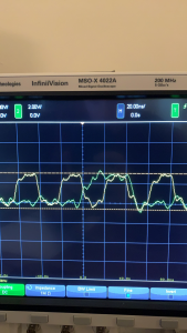
This image shows the timing and variance in the voltages. The clock line is in yellow and one of the data lines is in green.
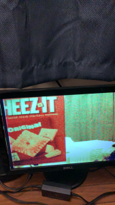
This image shows the working color output of the camera. The colors are slightly off (mainly in deep blues and greens) due to the white balance not being fine-tuned. This has since been rectified in the lighting of my room, however.