The primary risk to our project at the moment is the lag time associated with remote work. One team member’s already overslept and missed a morning meeting for discussing the ordering of one of the camera mount’s PCBs, and our Wednesday discussion this week was postponed by a substantial amount of time to accommodate the same team member’s breakfast. Even as I finish up this status report (barely an hour before it is due), one team member remains unresponsive to my messages even though a meeting was initially scheduled for 7 pm EST to do the report. This team member did not see fit to communicate a need to reschedule the meeting for a later time, or to keep the rest of the group up to date on their situation. The lack of punctuality (particularly in the case of morning meetings) is especially egregious in the context of one team member being in a time zone 3 hours behind the other two’s. This risk was originally managed by posting reminders of meeting times on the group chat, and explicitly confirming the times of future meetings before signing off from Zoom. However, since recent events have indicated that such measures are insufficient, I plan to collect phone numbers from team members and call missing group members at scheduled meeting times.
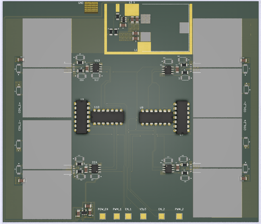
This week, the decision was made to change over to lower power unipolar stepper motors for driving the camera mount’s barn door compensator. This required the design and layout of an entirely new PCB for controlling said stepper motors and thus cost one of us a few days of time. This decision was justified by coronavirus-induced constraints on PCB fabrication, and the relatively lower torque requirements of a barn door compensator. The controller board associated with the original bipolar stepper motors was relatively large to accommodate the large currents needed for the motor windings, and would have needed to be fabricated by a Chinese manufacturer for us to remain in budget. Because the lower power unipolar stepper motors require less board area for heat sinking (and for the actual driver, since unipolar drivers are simpler than bipolar drivers), switching over to them allowed the affordable usage of a US-based PCB manufacturer that charged by the square inch and the avoidance of the undoubtedly long shipping times associated with overseas shipping at this time. Although the new unipolar stepper motors aren’t capable of providing as much torque as the original bipolar stepper motors, this is not an issue due to the lower torque requirements of a barn door compensator.
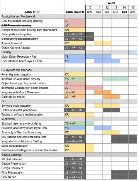
The updated Gantt chart for the remaining weeks of our project is as follows:
The majority of the assembly tasks have been delegated to Kenny, who has volunteered to integrate the mount components at his residence. Three tasks have been crossed out because of the change in the system design to a barn door tracker-based camera mount, and a task has been added for the investigation of Arduino-based alternatives for recording waveforms (since oscilloscopes are no longer available).
Updated Risk Management Plan:
Some notable risks for our project deal with failure to implement certain subsystems effectively or in a timely manner.
One risk we face is a failure to implement a working motor controller. This can happen due to several factors including stress and voltage spike test failures, and controller-driver interfacing errors. A solution for this subsystem failure would be to forgo implementing our own motor controller. Purchasing a driver controller module as a replacement would pose it’s own challenges as power distribution design would have to be altered to accommodate for the new module. We are also investigating means of debugging the motor controller upon arrival, in case there isn’t time to order a pre-packaged motor controller in the face of coronavirus-induced shipping delays. Thus far, this has taken the form of including means of monitoring the motor controller within the PCB (test points, current sensing resistors, etc.) and investigating the usage of an Arduino as a makeshift oscilloscope for interfacing to these means (now that an actual oscilloscope is no longer available).
In our original risk management plan, we mentioned a contingency for the failure of our project’s mechanical compensator in the form of a switch to a mechanically simple barn-door tracker-based compensator. Owing to the unavailability of CMU fabrication facilities and thus the inability to build our original design, this contingency has been implemented.
A third subsystem that could suffer failures is the computer vision software. If object-tracking is inaccurate, slow, or buggy, or if the latency of image transfer between the user-provided camera and the Raspberry Pi is too high to allow for real-time correction, real-time object-tracking will not be feasible. We can instead implement blind tracking based on known information about celestial objects or given input from the user. We could also repurpose the computer vision for drift alignment for polar alignment.
One major risk that has manifested in the move to remote work is the increased difficulty of debugging the software components of the project. The group member primarily responsible for our project’s computer vision routine is located in Pittsburgh, while the group member performing the integration of the mount’s hardware components is located in Miami, Florida. To alleviate the distance, we are investigating the possibility of setting up a ssh server on the camera mount’s Raspberry Pi so that remote debugging is possible for the person located in Pittsburgh. The principal challenge of this is making sure that the ssh server doesn’t compromise the security of the Miami-based group member’s network.
Fortunately, there are few new risks to the successful integration of the mount’s hardware. The team member in charge of physical assembly is familiar with both the mechanical and electrical sides of the project, and has assured the group that he is in possession of the equipment necessary to accomplish his tasks.
Regards,
Yuyi Shen
