This week, I designed and laid out for a unipolar stepper controller board for the MIKROE-1530 stepper motor, which we’re switching to due to its lower power requirements. Although ready-made drivers do in fact exist for this stepper motor, the more common ones rely on BJTs to switch current through the motor windings, which have relatively high Vce,sat values. As a result, the decision was made to specify a controller board with low Rds,on MOSFETs (IRLR6225TRPBF) to bring the board’s power dissipation to a minimum.
Because of the relatively low complexity of unipolar motor drivers, the design process was fairly simple, with the exception of the selection of gate resistor values for the motor driver MOSFETs for limiting the degree to which the current waveforms through adjacent motor phases overlap. This overlap manifests as periodic spikes in the current from the power supply, and needs to be kept to a minimum to avoid overloading whichever module is supplying power to the motor. LtSpice simulation was performed with the below testbench to determine the impact of the gate resistor on the supply current spikes (graphed below):
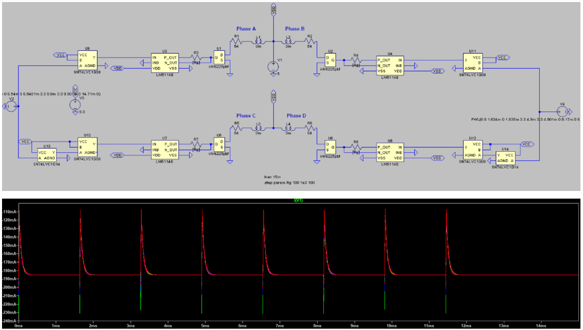
The magnitude of the spike (measured using the steady-state supply current of 185 mA as a reference) was found to be inversely proportional to the gate resistor value:
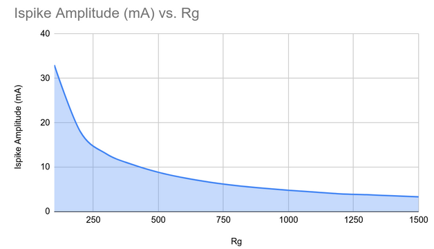
Ultimately, a gate resistor value of 475 Ohms was selected to keep the supply current within 5% of the steady-state value. The logic gates for providing the motor controller’s ENABLE functionality and hardwiring the motor’s full-step sequence were included in the simulation to model the impact of their propagation delays on the supply current spikes. After this was finalized, high-speed 1N4148 diodes were added in shunt with the MOSFET body diodes to serve as flyback diodes and a transient simulation was performed to confirm that the voltages at the MOSFET drains did not rise beyond the 20V limit for the MOSFETs:
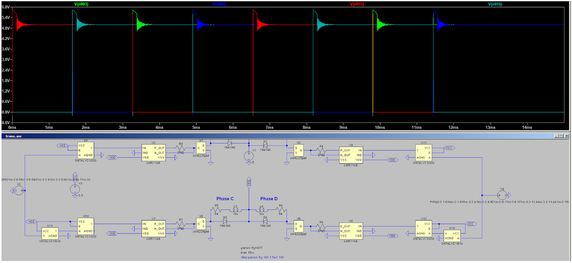
Because the current spikes through the flyback diodes do not exceed 92 mA in magnitude while the diodes themselves are rated for 2 A of surge current, this design is fine.
Unfortunately, due to a connection error during the layout, a revision had to be performed after the Google Form for the board order was submitted. The updated board order is linked here: https://oshpark.com/shared_projects/ezthQ1TM
The layout for the new motor controller board is shown here:
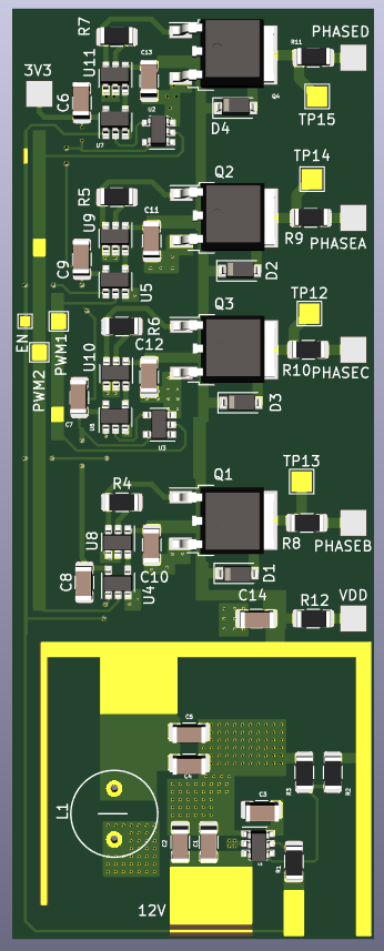
All IO pads on the board are surface mount, and so will require some skill from Kenny during assembly. Each logic input and the board outputs are equipped with either test points for debugging the board’s control inputs or current sensing resistors for measuring the board’s output current so that my SPICE simulations can be validated.
In addition to working on the motor controller for the mount, I also advised Kenny on the design of rudimentary constant-current drivers for the test setup’s laser diodes. To lower the strain on our budget and avoid the lead time associated with PCB fabrication, we chose to have Kenny solder together through-hole components in air for these drivers.
At present, I am on track with respect to our current schedule. Next week, I plan on going over the mount’s user interface with the others and designing a board based on their recommendations to serve as an electro-mechanical interface to the mount for the user. Thus far, we’ve been planning to use this interface board to permit the manual operation of the camera mount’s stepper motors and the selection of targets for object tracking.