Jamari’s Status Report for 4/25/26

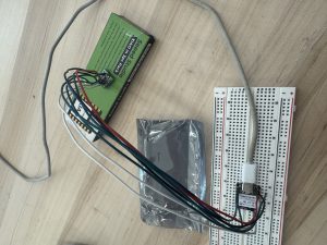
This week I have been working to test and integrate our force-sensitive resistor with our design. I did some experimenting to understand how it works, and with some help from Tsairus, decided to use a digital output pin to create a voltage divider with the FSR and internal pulldown resistor on the analog pin. Once I got that working and could see our likely range of voltage values, I made changes to our codebase to reflect expected functionality and integration with the system.

For next week, I will be preparing for the final demo and finishing up all other deliverables. I will do some more solo testing to verify different tip contact points with the FSR sensor, and as a team we will complete full integration testing for the final demo.
Tsairus’s Status Reports for 4/25/26

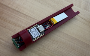
This week I spent most of the time testing the integration of the IMU and optical flow sensor with the MCU to make sure we were meeting our use case requirements. Most of the testing of those components are done and the main thing that needs to be completed now is tuning the sensitivity of the optical flow sensor and integrating the fsr with everything else. My progress is on schedule and my deliverable for next week is to finish the fsr stuff and finally finishing integrating everything inside the pen.

Team Status Report for 4/25/26

The most significant risk is the full integration of the FSR with the housing tip, and tuning the CPI in software, but these are being addressed with consistent testing and iteration. There were no significant changes made to the design, and our schedule is unchanged.

With our timing module tests, we found that our overall optical sensor to drawing latency is ~46ms, well within our 80ms requirement. Our CPI accuracy test yielded that a 45 degree tilt in sensor orientation from a horizontal orientation is within a 1% margin of error of the CPI with horizontal orientation. Our total weight, while not final yet, is ~40g, which is higher than our projected maximum of 30g, but this was a tradeoff for usability with more complex components. Measuring the current draw of our sensor combined with the MCU and battery resulted in an average active current draw of 23mA and an estimated battery life of 4.35hrs, well above our requirement of 2hrs.

Christian’s Status Report for 4/25/26

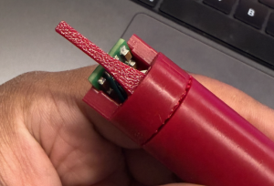
This week I’ve mainly been working on getting the tip mechanics for the stylus printed out, and helping with physically integrating the components. I’ve had some hiccups in getting the tip sturdy and stable since it is the only moving component in our design, but I am making progress and should be done with the integration within the next two days. We are almost ready for the final demo!

Jamari’s Status Report for 4/18/26

This week I was working on bluetooth communication and system integration. Currently, our implementation uses Human-Interface Device (HID), which is how digital stylus acts as an air mouse. However, this may cause problems when we start integrating our FSR for pen thickness, since a mouse cannot read analog push data.

My current implementation utilizes service + characteristic uuids to establish a connection between the MCU and computer, then send over data. One issue I ran into was getting both pygame & bleak (bluetooth library for python) to work together. This issue was fixed by implementing multi-threading into our python code, so both can run together without blocking. We will need to check if this introduces any latency issues compared to our current approach. I will work more to help Christian with FSR integration.

Per canvas, I’ve been able to learn more about bluetooth and the pygame application for canvasing. Learning these resources has often come from online articles to upstart code, videos for debugging help, and generative AI to help fill in conceptual gaps. I also reinforce my understanding through explaining to my teammates.

Christian’s Status Report for 4/18/26

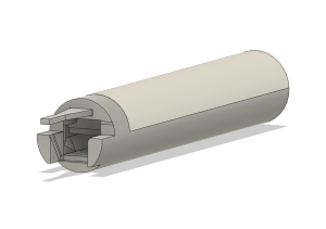
This week I made more refinements to the 3D housing. After brainstorming with teammates, we decided to keep the front part of the housing solid while only sliding the back portion.  This allows us to place the FSR statically in the front and have a sliding mechanism for the tip of the pen to push on the FSR. I redesigned the tip of the pen to be a separate print from the body so that we can snap in the tip to the front, and have it slide back and forth with a hook mechanism to have natural presses of the FSR. I also had to make the housing thicker because of quality control reasons with how thin the 3D printer in TechSpark.

My progress is on schedule, and next week I hope to have everything integrated in the housing.

As I’ve designed the project, I had to learn how to 3D CAD in Fusion360 to make the housing and make sure the housing adheres to design constraints. In addition, I had to learn how to interface with the OS HID reports to take in external Bluetooth data.  I learned how to do these things through trial and error, and also online information.

Team Status Report for 4/18/26

I think the biggest risk we are facing right now is figuring out the best way to integrate the force sensitive resistor (FSR) inside of the pen to allow for easier surface touch and liftoff detection. These risks are being managed by constantly integrating and revisiting the housing design to ensure we get the design for the FSR correct. The contingency plans we have so far is just use a button or two since these are easy to integrate or use the optical flow sensor and IMU together to figure out liftoff detection.

No new changes made to the design and our schedule remains the same.

Tsairus’s Status Reports for 4/18/26

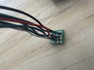
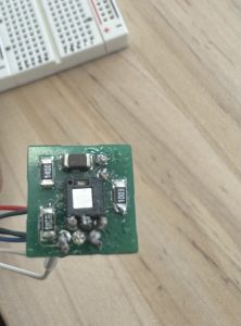
This week I managed to finish assembling the PCB together and doing all the necessary physical testing to make sure the PCB works. I also soldered the wires that we will use to the PCB to make it easier to connect everything to the MCU. When testing the PCB all of the voltages and connections were correct. Here are some pictures of the PCB:

In addition to this, I also wrote some code to test the PCB and MCU integrated together and I was able to successfully get the SPI communication working and the MCU was able to receive the x and y data from the optical flow sensor. One last thing I did was write some test Bluetooth code to see if the PCB and MCU could work together to move my computer mouse by communicating through Bluetooth and this test was successfully as well.

I am currently on schedule and the deliverables I hope to complete next week is integrate the force sensitive resistor with the PCB and MCU to make sure the pressure sensing works and do any last firmware clean up to maximize performance of our system. After that all that is left is just testing.

Week Specific Items

Some knowledge I found necessary to learn in order to accomplishes the task of the project was how IMUs and optical flow sensors worked because without this knowledge I would not have been able to effectively write firmware that could use these components. I also needed to learn more about sensor fusion since our project will be receiving data from different components like an IMU, optical flow sensor, and force sensitive resistor so understanding how to fuse all this data together was important for functionality. In addition to this, I needed to remind myself of good PCB habits since our project needed a very small scale custom PCB and there was not much room for error due to the time constraint. The learning strategies I used to obtain this knowledge is watching a lot of youtube videos and reading a ton of documentation and datasheets. I also used AI from time to time to explain concepts that I was unsure about like how optical flow sensors worked or what does connection interval on Bluetooth mean.

Team Status Report for 4/4/26

After completing the interim demo, we are finishing up the major development portion of our project and moving primarily into testing and verification. The main parts of the project we still need to include are the force-sensitive resistor (FSR) to simulate a pen writing when pressure is applied, and our optical flow sensor, which should be ready integrate with our new PCB.

For testing and verification, our primary tests to run are for latency, accuracy, battery, and weight + housing. For latency, we will have timing modules as data moves through our system, with end-to-end and round-time travel measured. Housing & weight will be gathered from user feedback during and outside of lab time. Once we have finished incorporating the (FSR) and optical sensor, we will conduct writing sessions to measure battery. We should be in a good place to incorporate any feedback from stakeholders.

Jamari’s Status Report for 4/4/26

For this week, I have mainly focused on slight debugging for our canvas application to avoid off screen bugs and coordinating our verification & validation plan. I am currently working on our latency testing through setting up timing modules in our code. As we continue to reiterate our housing design, I also want to tackle our weight + physical design requirements by incorporating user feedback into our future designs.

For the upcoming week, I will continue with latency verification and housing validation. In terms of core functionality, I will also help on the software side of integrating our force resistor and full system integration.