Team Status Report for 4/6

Risk and Plans

Continuing from last week, we are making good progress on the software, UI, and hardware connection of the devices. In addition to the risks that were discussed in last week’s report, the biggest risk right now is to make sure that our system will meet the design requirements that we set up. We are just starting the final system integrations. Although individual complements are functioning, we are still unaware of the functionality of the full system. We need to run validation tests to ensure the specs are met. However, since we have limited time, if the system performs suboptimal, we do not have a lot of time to address the issue, which could jeopardize the project. To mitigate this risk, we have adjusted the schedule so that we can keep on track with the system integration. This allows us to start validation testing of the whole system as soon as possible. We have done some good research and implementations on the individual comments based on our requirements, which is a positive aspect to ensure the design of our system will meet the requirements in the end.

Changes in Design

No changes to the design this past week.

Schedule Updates

Here is an image of our updated Gantt chart for this week:

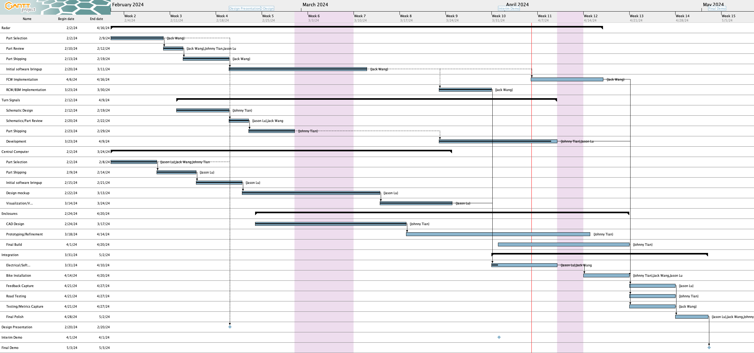
Here are the schedule updates since last week:

Completed tasks :tada:

  • Enclosure CAD designs
  • RCW/BSM radar implementation

Delayed tasks :alarm_clock:

We forgot to account for no work during Carnival previously, but that is now accounted for. Unfortunately, with all the schedule changes we have no more slack time.

  • Radar tuning – We’ve shifted FCW radar implementation to run in parallel with electrical/software integration and final bike installation due to delays
  • Turn signal development – Turn signal development has been extended to this upcoming Wednesday (4/10) to give Jason time to work out the remaining issue. We’ve also shifted this to run in parallel with electrical/software integration and final bike installation
  • Enclosure prototyping/final build – We’ve extended those deadlines and changed them to run in parallel with electrical/software integration and final bike installation
  • Total time for polishing has been decreased from 7 to 5 days

At risk

  • Electrical/software integration is a little delayed but we may be able to finish it on time. However, we need to be careful not to slip on this, although if it’s just software left to be integrated we can run it in parallel with bike installation

Planned Validation

  1. Radar:
    1. Detection Accuracy: We are planning to validate the radar detection results on the full system to determine if it meets the Radar Accuracy Confusion Matrix discussed in the design report. This will be done by riding the bike with the system installed and recording the number of warning triggers in a run. We will video-record the test run so that we have the ground truth of the environment. We will then compare the warnings and the ground truth to calculate the false negative and positive rates of the system to validate the setup.
    2. Maximum Range: After mounting the system on a bicycle, we can park a car and have a measuring tape extended out from the front of the vehicle. Then, with the bicycle moving backwards towards the vehicle parallel to the measuring tape, we can see where along the measuring tape the system first picks up the car.
    3. Distance Accuracy: This is similar to the range check, except we continue to move closer to the car once it’s picked up and verify that what the system is reporting is close to the distance from the car as indicated by the measuring tape.
    4. Speed Accuracy: We will have a driver drive a vehicle past the radar (which is stationary) at a fixed speed. Then, we’ll check that the reported speed is within the accuracy requirement.
    5. Data Update Frequency: To ensure the radar data update frequency is at least 10 Hz, we will have the radar be stationary and have a car drive slowly towards it. Then, we will see how often we receive updates about the car’s distance by counting the number of data updates from the radar to the UI in a certain time period.
  2. To validate the durability of our bike safety hub system, we will ensure it’s able to run for two hours with our power bank. This involves both lab and real-world scenarios to ensure functionality and durability in typical usage conditions.
  3. To assess the waterproofing of the final enclosure, we will conduct a series of tests gradually increasing in difficulty. Starting with a slight sprinkling to simulate light rain, we will then progress to more challenging conditions, ultimately reaching an IPX4 rain test level. This comprehensive approach ensures that the enclosure can effectively withstand varying levels of moisture exposure, guaranteeing its durability and reliability in diverse environmental conditions.

Jack Wang’s Status Report for 4/6/24

Personal Accomplishments:

  1. Interim Demo Set Up (2 hrs): I spent some time this week setting up the radar portion of the interim demo.  In addition to plotting the data points, I printed out the possible warning types (collision/blind spot) based on the location of the target. I then presented the setup on Monday.
  2. Radar Tuning and UI Integration (10 hrs): I spent the majority of time last week processing the radar signals to make them useful for our needs and integrating the radar with the UI that Jason has been doing. I discussed with Jason about what is the relevant data that should be sent to the UI and how to pack the data. We agreed that I would be doing the majority of the data processing. Specifically for the rear radar, I will divide the region into three sectors as discussed before. For the areas of blind spot detection, I will send a positive flag if the radar detects an object within the threshold. This is because the UI only cares if there is an object approaching the “blind spot” and does not require detailed information; for the region of rear collision detection, I will send over the object that has the closest absolute distance to the bike, where the UI will be using the distance and velocity information to alert the rider of a possible collision. I discovered that we could use Named Pipe to send the information between my radar processing script in Python and Jason’s UI implementation in JavaScript. I packed the data into JSON format and did some basic testing with Jason to verify the communication. As of Friday, we were able to transfer data from the radar detection script to the UI.

Progress:

I finished the radar tuning and some basic UI integration, so I am on track for now. I will be taking over Jason’s task of tuning the forward radar, given the similarity of its functionality to the rear radar. This is to keep us on track with system integration. The latest schedule in our group report reflected this change.

Verification

  1. Basic Radar Detection: I have run some tests to benchmark the basic functionality of the radar. This was done by setting up the radar in a controlled environment and having people running/walking toward the radar from different angles to simulate incoming traffic. Using the plot generated, I verified that the radar could accurately detect the approaching people with reasonable distance output. The result is analyzed by recording the output x-y distance that the radar is reporting and comparing them with the actual location of the people, which is measured with meter sticks. This data is used to benchmark the metrics mentioned in the Radar Accuracy Baseline section of the design report. This verification task indicated the basic functional success of my radar implementation.
  2. Integration Verification: I verified that the output data of the radar was correctly communicated with the UI. This was done by printing out the raw data in the radar processing script and the information that the UI received. This is to make sure that the system is updating data correctly, which indicates the functionality of the communication pipeline.
  3. Radar Detection in Real World Environment: This will be a verification task that I will do soon, since I just finished tuning the rear radar. The goal of this verification task is to make sure that the radar will provide the desired detection results in the real traffic environment. I will mount the radar onto the bike and drive a car approaching the bike in a parking lot. I will then analyze the result to see if the radar output makes sense. This includes comparing the distance and the velocity output of the radar with the ground truth data, which is measured by tape measure and speedometer.

Next Week:

  1. Integration
  2. FCW radar tuning

Jason Lu’s Status Report for 4/6

This Week’s Work

  • Implemented physical control of turn signal lights
  • Implemented auto-cancellation using magnetometer
  • Started integration with Jack’s radar code

For details, please see the “State of the UI” section below.

Schedule

Out of the two deliverables from last week, I partially completed one (in orange) and did not make any progress on the last task (in red).

  1. Complete implementation of turn signal control
  2. Complete radar implementation

The only real work remaining for the turn signal stuff on my end is to mitigate the issue where we need to physically turn the compass 90 degrees for it to report a change of 60 degrees – I have a potential workaround (see below)

However, I am behind on the radar implementation task. I will check with Jack on whether this is something he can take on, since theoretically we can reuse the stuff he does for the RCW specifically for the FCW. I’m also realizing it is somewhat ill-defined what radar implementation is – I think a good definition at this point is to have code to filter the points from the radar, identify which of them correspond to a vehicle directly in front (for FCW), and send the distance and relative velocity of that car to the UI.

Upcoming Deliverables

The deliverables for this week are similar to last week’s, except changing “radar implementation” to “radar and UI integration”.

  1. Complete implementation of turn signal control
  2. Complete radar and UI integration

State of the UI

Here’s a more detailed rundown of what the state of the UI is as of the time of this writing.

Turn Signal Lights

I implemented code to drive the actual turn signal lights through GPIO pins which in turn control transistor gates. There is a minor issue where the on-screen turn signal indicator isn’t synchronized with the physical turn signal light, but for now it should be OK.

Turn Signal Auto-Cancellation

For our turn signal auto-cancellation system, we are using the Adafruit MMC5603 Triple-Axis Magnetometer as a compass. As a quick refresher, the idea of using the compass is that when we activate a turn signal, we record the current bicycle heading. Then, once the bicycle turns beyond a certain angle (currently targeting +- 60 degrees of the starting heading) we automatically turn off the turn signals.

Adafruit provides libraries for Arduino and Python, but since the UI code is written in Javascript there weren’t any pre-written libraries. Therefore, I ended up writing my own code to interface with it.

As mentioned last week, I’m using the i2c-bus library to communicate with the MMC5603 chip over I2C. With help from the MMC5603 datasheet and Adafruit’s C++ library for the MMC5603, we now have support for obtaining the raw magnetic field measurements from the MMC5603.

To convert those raw readings into a heading, I implemented the algorithm described in this Digilent article.

There is an issue where rotating the magnetometer reports 60 degrees of angle change only when it’s actually rotated 90 degrees. We can work around this in code right now by setting a lower threshold to auto-cancel the turn signal (perhaps 40 degrees so it’ll turn off when the bicycle rotates 60 degrees physically), but we may need calibration. From what I briefly read online though, this won’t be a simple process.

I also implemented the ability to override the bike angle to some fake angle in the debug menu. Here’s a video I recorded (a CMU account is required) showing the overriding angle feature and the turn signal auto-cancellation.

Integration with radar

The UI side is ready to receive real radar data! The general overview is that Jack’s code will do all the data processing, identify one vehicle each in front, behind, left, and right, and send their distances and velocities in a JSON string to my program. We will be using named pipes, created using mkfifo.

On the UI side, I based my code off of this StackOverflow answer. There was a slight hiccup initially when we were testing passing data from Python to JavaScript when the Python side seemed to buffer multiple JSON strings before actually sending them over the pipe, resulting in a crash on the Javascript side as it received a single string with multiple objects at the top level which isn’t valid JSON. We fixed this by inserting a flush call after sending each string on the Python side.