Eric Status Report – 3/9

In the beginning of this week, most of my time was spent working on the team’s design review report. In addition to writing my contribution to the report content, I compiled and formatted the document at the end. The Raspberry Pi order has still not arrived yet, so I am still unable to directly work with the Pi. I created a GitHub repository for the team’s code, and continued working on the code for the motor controls. I am encountering some difficulties in using the library, which I may need to solve by installing Linux on my computer.

My progress is a bit behind schedule, because I was unable to complete most of the motor control code before Spring Break began. To make up for it, I will push myself to complete the code soon after break ends. The process will also surely be expedited by the arrival of the Pi and being able to actually test the code. In the week after break ends, I plan to finish the majority of the code for the motor controls and test it on the Pi once it arrives.
Chris Status Report – 3/9

My work this week was mostly focused on contributing to our design document, but outside of this I continued iterating on the 3D part designs and created a template of the routines which need to be developed in python. I printed the initial design of the carriage pat, but due to some size and tolerance issues from printing, the two halves were not able to mate properly. I updated the design to accommodate this but the issue was still present. This issue has been difficult to fix, as each design iteration takes at least a day to verify due to having to wait for the print. Currently, these design issues have set me back slightly and to make up for this I can start printing beta versions of every single part at the start of the next week, to allow for all parts to be finalized and for the full assembly of the gantry to begin.

Additionally I began creating the outline of our software layer and created all of the files we will need to operate the gantry. These files finalize the interface designs between the different components of the software layers and allow us to test each section of the code individually. My contribution to this in the coming weeks will be to develop a simple model replacing the operation of the gantry, which will allow us to test the image processing and stroke generation algorithm.

Overall I have fallen slightly behind on schedule this week, as I have not been able to finalize all of the 3D designs. In the upcoming week I hope to catch up on this, begin assembly of the gantry once the parts arrive, and develop a simple model of the gantry control layer for use in testing the painting algorithms.

Team Status Report – 3/9

This week our team was mostly focused on creating our design document, which consumed most of our time in addition to the discussion we had during class on Monday. None of our new parts arrived, but we have completed ordering all of the requisite parts and should all arrive by after break.

No new risks have developed for our project as a whole, but we are still faced with risks regarding the success of completing the gantry and having an effective mapping from the digital image to series of paint strokes. These portions are being mitigated by us concentrating our efforts on these goals continuously.

Minor changes have been made to our design, and the total design has been finalized with the completion of our design document. Our gantry will now operate on special watercolor paper which should be more robust to warping. This has dimensions of 5×7 inches, meaning we have much more space available in the design of our board. The interface layers have also been finalized, where the gantry control layer exposes an initialization function and a draw stroke function, which are the only means of communication with the painting algorithm, allowing it to be controlled very simply.

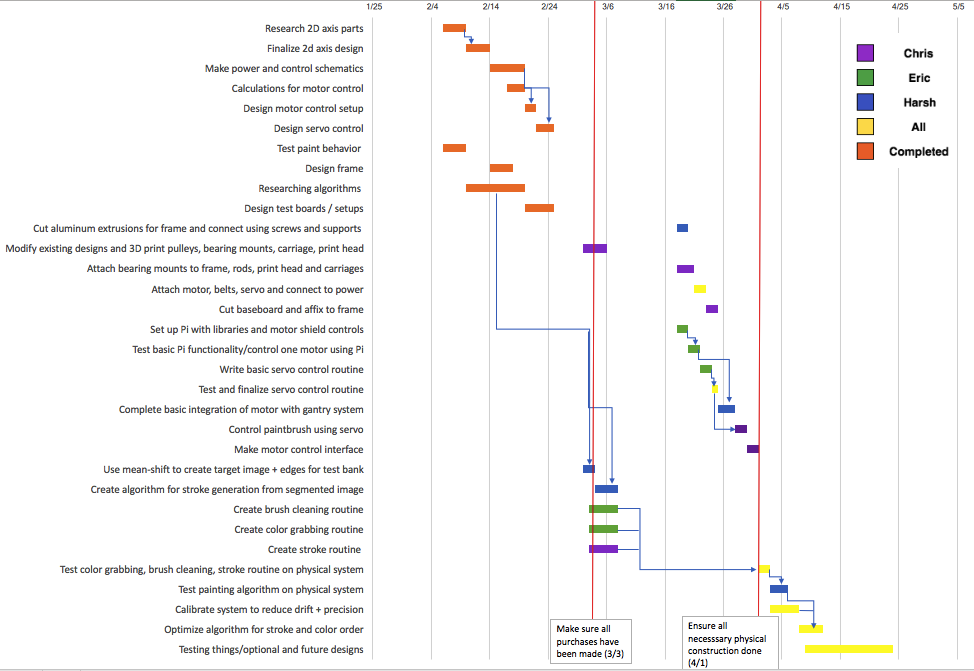
This week we were not able to move forward as much as we would have liked due to the significant portion of work of creating the design document and our parts not arriving. An order mixup resulted in us not receiving our bearings, which meant we were not able to test compatibility of the shafts with the bearings or test the 3D printed bearing mounts. Our schedule has also been updated as of the design document and the most up-to-date schedule is included here.


Harsh Status Report – 3/2

This week I spent most of my time working on the design review report. Since I had done the design review presentation, I had a good idea of what to put into the design review report. One of the criticisms from Professor Nace was that our schedules weren’t precise enough, so I spent some time making a more detailed and better formatted schedule.

One of the things we realized was that the time constraint of 8 hours for all images didn’t make sense and was too vague. Therefore I, with Chris’ input, created a new way of measuring how much the time constraint for a specific image should be. It is based on the complexity of the image. The way to measure complexity in the image is based on the ratio of compression of the jpeg version of the image and the size of the image. The more it can be compressed, the simpler the image is. I also cut the shafts to the desired lengths for the gantry system.

My goal for the next week is to run the image segmentation algorithm on the test bank and save the results. The biggest task for me will be to create the stroke generation algorithm. This is the algorithm that takes the output from the image segmentation and turns it into a list of strokes for the robot to do.

I was supposed to start the stroke generation routine and creating the image bank yesterday but I had to push this back by a couple days in order to complete the design review report. I will start working on these tomorrow. In case I don’t finish, I will work on this over Spring Break.

Harsh Status Report – 2/23

This week I worked on finalizing the software algorithm after meeting with Professor Aswin Sankaranarayanan. We have decided to go ahead with Mean Shift Segmentation clustering algorithm to pre-process the original image into something that we can draw using our robot. We will start with the lowest detail segments first, and then overlay the high detail ones on top of that. We are also thinking about creating a bank of strokes which will allow us to draw and fill in the shapes that we need. Any parameters (such as how large the segments should be, how many colors, finalizing of the stroke bank) will be finalized during experimentation once we have built the robot.

I also created the painter head which will house the servo holding the paintbrush on Solidworks. We will finalize the measurements once we receive our servo, but the design is complete. Furthermore, I worked on the Design Review slides and Document. I will be giving the presentation on Monday and so I’ve been preparing for that as well. One of the diagrams that will go into the design document was prepared by me.

I am on schedule with everything. Next week, after the design review, I will help with 3D printing of the parts and building the gantry system. Nothing needs to be done with software until we have built the system.

Harsh Status Report – 2/16

I spent the first part of the week helping Chris and Eric research 2D axis parts and design. I spent some time reviewing what the team had found and suggesting some alternatives. I also helped them decide whether we should 3D print most of the parts or order the parts from online. After this, we wanted to 3D print a part to test its precision and quality. I aided in the conversion of the files into a format that could be accepted by the printer in the Morewood Makerspace.

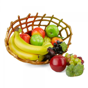
During the last part of the week, I worked on implementing and testing the Mean Shift Segmentation algorithm. This is the algorithm that we are planning to use to turn our original digital images into something that the robot can paint. As we mentioned during our proposal presentation, this algorithm clusters similar colors together and returns an image with segments of the same color. I implemented this using the pymeanshift python library. Below is the original image:


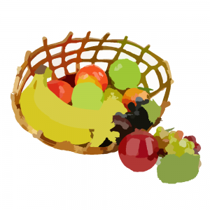
The next image is one with a tight color range:


The following is one with a large color range in one segment:


We can change the parameters depending on how many colors we will have access to when we start creating our paint colors. I have emailed Professor Aswin Sankaranarayanan to discuss tips and ideas about possible imaging algorithms we could use.

My goal for next week is to meet with Professor Sankaranarayanan and finalize an algorithm to use for this project. I will then test it on different images with various parameters to make sure we can get the right images. I will also help the team order the parts we need for the 2D axis and 3D print some of the required parts.

We are mostly on schedule. We have researched the software algorithms. However, I have extended it by a few days to compensate for meeting with Professor Sankaranarayanan next week. We’ve also finished researching and designing the 2D axis, so we are on schedule for that.

Introduction to our Project

Welcome to our team’s blog! Our project is a robot that can take a digital image and then paint a watercolor version of that image on a physical canvas. The aim of our project is to create an image which looks like a naturally painted image, not a replica of the source image. At a minimum this product will be able to represent simple images or match the shape of the given image. The resulting image should be similar in terms of color gradients and general appearance and contrast. To build this, we are using a 2-dimensional system to physically draw the picture along with a software component that will allow us to turn the digital image into a painting.