Team Status Report – 2/23

This week, we finalized the design for our 2D gantry system, as well as the frame of the robot. We started ordering many parts, including the Raspberry Pi, the motors, a paint set, and shafts and bearings for the axis system. We worked on our design review presentation, and created several diagrams and schematics for it. In addition, our team met with Professor Aswin Sankaranarayanan to get input on the image processing aspect of our project and discuss our software algorithm.

The most significant risks of our project continue to include the success of our 2D gantry system, which was discussed in last week’s report. We will continue with the plan we have in place, with our backup plans still ready. Once the parts we’ve ordered have arrived, we can begin constructing the system, and adjust our approach and design based on any problems we may encounter during that process. Another risk was brought up once we discussed our project with Professor Sankaranarayanan, who discussed certain difficulties in creating a painting robot. Specifically, he mentioned the main three things to consider would be the clustering algorithm, the color intensity, and the brush width. He gave us some advice in dealing with each issue, and we discussed the potential approaches and solutions amongst our team. Due to the difficulty in some of the image processing considerations, there are risks in how successfully we can translate a digital image to painting. We decided to keep our initial approach, which is based around the mean shift segmentation algorithm. However, if this fails, we can use any of several other clustering algorithms, with k-means being a viable backup. Regarding color intensity and brush width, there are several alterations we could potentially make to our painting procedure if either of these are an issue. We could modify our approach to only deal with silhouettes, only use edge detection and paint the edges of the input image, or just reduce the detail we recreate in our painting. Our painting head is designed so that it can hold pencils, paintbrushes, etc.

No significant changes were made to the existing design of the system, although we did finalize decisions on the hardware component of our project as well as how to power the robot. No changes have occurred to our planned schedule, as we are all on track with our progress.

Eric Status Report – 2/23

This week, I finalized decisions on which hardware parts to use, specifically the stepper motors and servomotor. As a team, we placed orders for these parts as well as many others. I did research on how to power our project, such as how to power the Pi and how the pi would connect to the motors. As a team, we found a rather simple solution for both, as the motors can be attached easily to the motor shield of the Pi and a simple cable can be bought to power the Pi from an outlet. In addition, I created the parts spreadsheet for our team, which keeps track of the parts we’ve ordered and received, how much we spend on each part, our remaining budget, and other things. I worked on the team’s design presentation for Monday, and specifically I contributed by creating a block diagram for the design review. I also started working on an initial draft of the image bank we plan to use for some of our testing metrics. I did research into the best way to test our robot’s ability to choose color, and concluded a system that involves testing for the nearest HSV value.

My progress is on schedule. For the next week, we will finalize the image bank we will use for testing. Once our parts arrive, I will start testing and experimenting with the RPi libraries for Python, and begin writing code to control the motors. As a team, we will also begin assembling our frame and gantry system once the parts for it arrive.

Harsh Status Report – 2/23

This week I worked on finalizing the software algorithm after meeting with Professor Aswin Sankaranarayanan. We have decided to go ahead with Mean Shift Segmentation clustering algorithm to pre-process the original image into something that we can draw using our robot. We will start with the lowest detail segments first, and then overlay the high detail ones on top of that. We are also thinking about creating a bank of strokes which will allow us to draw and fill in the shapes that we need. Any parameters (such as how large the segments should be, how many colors, finalizing of the stroke bank) will be finalized during experimentation once we have built the robot.

I also created the painter head which will house the servo holding the paintbrush on Solidworks. We will finalize the measurements once we receive our servo, but the design is complete. Furthermore, I worked on the Design Review slides and Document. I will be giving the presentation on Monday and so I’ve been preparing for that as well. One of the diagrams that will go into the design document was prepared by me.

I am on schedule with everything. Next week, after the design review, I will help with 3D printing of the parts and building the gantry system. Nothing needs to be done with software until we have built the system.

Chris Status Report – 2/23

This week I focused on ordering parts, creating and finding CAD files for use in the frame, and finalizing the design for the frame. We were able to order a majority of the parts we need this week, and hopefully they will arrive soon so that we can begin shifting to the assembly and early programming. Many were ordered through Amazon so this should be the case with 2-day shipping. I also continued modifying some of the Ultimaker files and found more to use which are compatible with the ordered parts, including some to house the bearings externally on the support frame. The design of the support frame has also been finalized and the parts are ready to be ordered, although the order has not been placed yet. The frame will be constructed primarily out of T-slotted aluminum which allows for easy connections and adjustments should they be necessary down the line. After ordering the parts our power needs were also clear and I worked on resolving how the entire gantry and pi setup would be powered. Additionally I have begun working on putting all of the parts into an assembly for easy viewing and modifying.

Overall this week I was on schedule. In addition to what is listed above we all worked on creating the slides for the design review and met with Professor Sankaranarayanan. Next week I will complete the assembly of all the parts and begin basic assembly and 3d printing once the parts arrive.

Team Status Report – 2/16

The most significant risks that could jeopardize our project is the failure to successfully create the 2D axis gantry system. The three of us are confident in our ability to write a working software algorithm with our experience, but we all lack any significant experience in robotics or mechanical engineering. As a result, we are frontloading the work for the physical aspect of our project, which includes assembling the actual robot as well as getting the hardware component functioning properly.  Right now, we are considering several alternatives for procuring the parts necessary for the creation of our gantry system, which is inspired by the gantry system used in Ultimaker 3D printers. Our current plan is to use CAD files that we found online of the Ultimaker gantry parts, such as screws and pulleys, and then customize them to our project specifications and 3D print them. In this approach, we would purchase more generic parts, such as rods and belts, from any source we want that would fit with our modified parts. The risks with this approach are possible structural weaknesses from using the 3D printer filament, possible inaccuracies from 3D printing small parts, and also the danger of parts not fitting together after our customizations. To mitigate these risks, we will test 3D printed parts for their sturdiness and how accurately the smaller details of a part are printed. We will also limit the amount of modifications we make to the parts to reduce the risk of breaking the system. We have several backup plans for obtaining the parts in the situation that our primary plan fails. One alternative is ordering official Ultimaker replacement parts to assemble our gantry system with. However, this approach would limit the customization available to us. On the other hand, it is almost a guarantee that the parts would work and fit together, due to being official replacements. A third possibility is ordering the parts online, but not necessarily all from a single source. We are thinking of using some of the more detailed Ultimaker replacement parts, such as pulleys and sliding blocks, but purchasing more generic components such as belts and rods from other sources. This would allow us to find belts or rods of our desired length, while giving us some freedom to customize. A drawback of this is that it is somewhat difficult to find some parts with certain specifications – for example, finding rods of a 8mm diameter that would fit with the Ultimaker parts.

We did not previously lock down many specifics for our design, so nothing significant has changed from our vision for the project and the requirements we detailed in our proposal. However, we are beginning to finalize decisions for the parts we plan to use as well as the specifications for our system, and how all the parts will fit together.

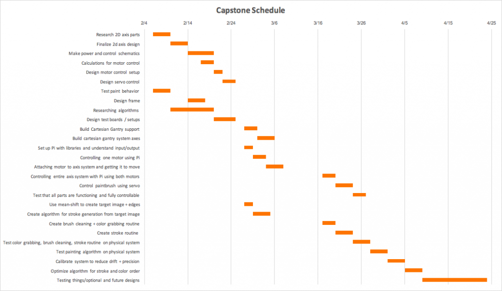
Below is our updated schedule:

Eric Status Report – 2/16

This week, I discussed designs with the team and helped look for parts we could use in our project. I helped in discussions which weighed alternatives in how we will procure the parts for the 2D gantry system, such as considering the tradeoffs of 3D printing some parts. I helped 3D print a modified pulley part that originated from an Ultimaker CAD file. Inspecting it and experimenting with it, we found it to be fairly durable. However, it was noted to have some imperfections.

The part is shown in the picture above, and the 3D printer printed it from bottom to top in the orientation shown in the picture. The bottom of the middle ring is notably not flat, due to there being no support underneath which caused the material to drip when the ring was initially being created. In contrast, the top of the ring is flat and smooth. The topmost part of the pulley in the picture orientation is also more rough and less even than the bottom piece, again due to lacking support during the printing. We brainstormed a method of rectifying this, which involves creating a structurally weak support underneath these components so that the material will not drip down while being printed. However, our overall assessment was that the part is sturdy enough and the defects are not significant (as well as probably being eliminated in the future), which makes 3D printing a viable solution to our securement of parts for our gantry.

For the rest of the physical robot, our team also did research and brainstorming for the bottom part of the base, as well as how the 2D gantry component would be stabilized. My personal research was looking into the type of beams we would use to hold the gantry up. I looked into aluminum beams, specifically the T-slot beams that our team first considered using during preliminary research. I compared alternatives from different vendors, as well as considered buying separate beams or longer ones that we would then cut down.

I also spent time preparing for the hardware component of our project, which was the primary division of the work that was assigned to me. I researched and read about the different raspberry pi libraries for Python that we are considering using, namely gpiozero and RPi.GPIO. Comparing these two options, I have found opinions online that point to gpiozero being the superior library due to simplicity and other advantages. I looked through documentation for both libraries and studied some examples. In addition, I looked into the hardware parts that we plan to buy, such as the stepper motors and servomotor. We are considering buying the same stepper motors that are found in Ultimakers due to using many other Ultimaker parts in our design, unless we can find a cheaper or significantly better alternative.

My progress is generally on schedule, although our initial schedule has making power and control schematics finished tomorrow, which we may need more time with. In order to catch up to our schedule, my team and I will primarily focus our efforts on the power schematics and hardware designs in the next few days, as we have mostly wrapped up the design for our 2D gantry system.

For the next week, I hope to finalize decisions for hardware parts we plan to use, finalize power schematics, and start performing calculations for the motor control. As a team, we will also work on finalizing the design for our frame.

Harsh Status Report – 2/16

I spent the first part of the week helping Chris and Eric research 2D axis parts and design. I spent some time reviewing what the team had found and suggesting some alternatives. I also helped them decide whether we should 3D print most of the parts or order the parts from online. After this, we wanted to 3D print a part to test its precision and quality. I aided in the conversion of the files into a format that could be accepted by the printer in the Morewood Makerspace.

During the last part of the week, I worked on implementing and testing the Mean Shift Segmentation algorithm. This is the algorithm that we are planning to use to turn our original digital images into something that the robot can paint. As we mentioned during our proposal presentation, this algorithm clusters similar colors together and returns an image with segments of the same color. I implemented this using the pymeanshift python library. Below is the original image:


The next image is one with a tight color range:


The following is one with a large color range in one segment:


We can change the parameters depending on how many colors we will have access to when we start creating our paint colors. I have emailed Professor Aswin Sankaranarayanan to discuss tips and ideas about possible imaging algorithms we could use.

My goal for next week is to meet with Professor Sankaranarayanan and finalize an algorithm to use for this project. I will then test it on different images with various parameters to make sure we can get the right images. I will also help the team order the parts we need for the 2D axis and 3D print some of the required parts.

We are mostly on schedule. We have researched the software algorithms. However, I have extended it by a few days to compensate for meeting with Professor Sankaranarayanan next week. We’ve also finished researching and designing the 2D axis, so we are on schedule for that.

Chris Status Report – 2/16

This week I was primarily working on finalizing our design for our 2d gantry system and beginning to look for parts to begin construction. To begin this process we looked towards existing 3d printer designs, and found a page that documented several of the most basic and popular designs in 3d printers. All of the products used belts rather than threaded rods, as they seemed to operate faster and be easier to use with a stepper motor. Based on this we’ve decided to utilize a design with belts, and more specifically to follow the design of the Ultimaker models, as shown in the image below.

A major benefit of this design is that Ultimaker is an open source company, and all of the CAD files for the requisite parts are available online. After deciding on this design and finding exact measures of all of the parts I spent some time looking at what parts are available online. There was some trouble here as many of the official Ultimaker parts are sold with a huge markup and are not sold in the US, meaning shipping times and costs would eat away at our project. To circumvent this we have decided to modify the CAD files available to work with more generic parts which would be easy to obtain, and also allow us to customize the design to the needs of our project. We tried printing one of the modified parts to test for strength and print quality, which is pictured below.

The pulley pictured above is meant to have a rod through the center and to have a belt around the teeth. Based on this initial print, it seems that the 3d printed parts are durable and accurate enough to work in the final project.

I also began trying to design the frame and support of the gantry system, but have not finalized any decisions regarding that. Overall this week I was on schedule, as I was able to finalize how our gantry would work, found retailors to purchase generic copies, and tested 3d printing and began modifications. Mostly what I will be focusing on this upcoming week is finalizing those plans and ordering the basic parts associated with the Ultimaker design. Additionally I will make the modifications needed to the CAD files we have found and 3d print a majority of the initial parts we will need.