Christian’s Status Report for 2/21/26

This week I was able to get the first physical 3D print for our stylus housing and start on the next iteration, as well as update our conversion module plan.
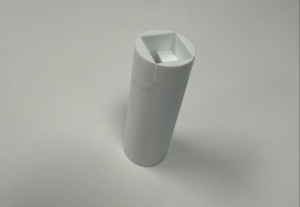
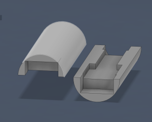
Our current stylus housing is a bit short, but the thickness of it sits comfortably in the hand. Even though we don’t have our MCU yet, I personally have a different MCU model from the same company that has the same dimensions, so I was able to test the fit of the housing with that. Within this next week, in addition to making the stylus longer, I am splitting the body in two to make it easier to insert and remove parts. I will also rearrange the positioning of the parts some to account for our IMU needing to be tested in variable positions to get the most accurate reading in relation to hand motion.
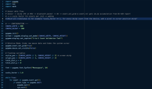
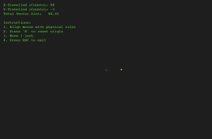
In terms of the conversion module, I came upon a really great Python library called pygame that natively works with the OS to use pixels as its measurement distance and directly grabs dx/dy data from the Bluetooth device buffer before it’s optimized by the OS. This simplifies the work needed to be done for our conversion module, and allows me to focus more on helping make sure our MCU and sensor outputs the optimal CPI for our application so that our users have a smooth drawing experience. I used Gemini to help with making a test program that measures x and y differences of CPI and pixel counts using the pygame library.
Progress is going well, I just need to send in the next iteration of our 3D print this weekend.
 

Christian’s Status Report for 2/14/26

This week I completed the first draft iteration of our stylus parts housing, and started on the conversion module for our physical distance to pixel distance software module.

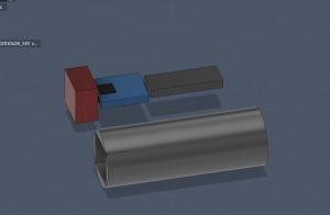
For the stylus housing, I imported a 3D CAD for the MCU we are using and formed a 3D block dimension for the MCU’s board. Since we are still leaning towards using the optical motion sensor rather than relying only on the IMU, I included a block for the PWM optical sensor that accounts for the ~1mm clearance needed for the sensor to work. I also included a block for our rechargeable Li-ion battery. I then formed the first iteration of our stylus housing around the dimensions of these parts.

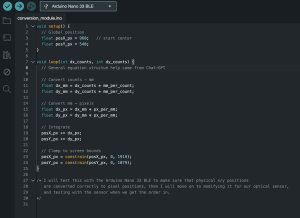
For the conversion module, I started on the basic math needed to take x-y data from an external controller and convert it to distance on a computer screen with bounding boxes. The actual steps needed to implement this conversion are quite simple, so the real challenge will come from tuning these equations when we test with whichever motion sensor we order.

Progress this week is a bit behind because I needed to get used to using Fusion360 again after about a year. I will ensure I’m caught up by cutting the 3D CAD iteration time in half by potentially using multiple 3D printers at a time if resources allow for it.

In this next week I plan to test the fit of our initial housing iteration with some similarly sized MCU and sensor parts, and I further improve and iterate the design by adding sections for buttons and slots to more firmly hold our parts together. I will also test the current conversion module with an Arduino Nano microcontroller to make sure that the baseline equations work well before we move on to the optical sensor.

Christian’s Status Report for 2/7/26

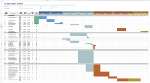
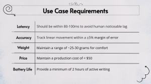
This week I helped specify use case requirements for our project to ensure that our MVP is indeed viable, including tallying up the weight, price, and helping estimate the latency requirements to look towards how usable our product will be. In addition to this, I planned out our semester work schedule in the gantt chart, and recently edited it to account for our shifted work schedule.

Within the next week, I hope to have a rough draft of both the physical position to digital position conversion module and the 3D print housing CAD done. As long as I start on these two things this weekend, I should be on schedule.