Bethel’s Status Report for 2/25/2023

What did you personally accomplish this week on the project? Give files or photos that demonstrate your progress. Prove to the reader that you put sufficient effort into the project over the course of the week (12+ hours). 

Progress from Last Week

A highlight from this week was my teammate Sophia’s successful presentation of our design slides on Monday. On the other hand, I had planned to finish transferring the game code from Javascript, HTML and CSS to Node JS as well as start tracking the coordinates and game actions of the different enemies within the game this week; however, this has proven to be more challenging than I had initially anticipated.  

I am primarily having difficulty translating the AI code from Javascript to Node JS. The AI serves the purpose of generating different Athenians to flock to the player within the game, creating new terrain as the player moves in different directions, among many other functions.

Considering this setback, I will be debugging the errors I am encountering before moving on to listening for the game events of different sized enemies within The Last Spartan.  


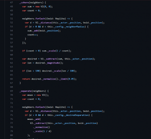
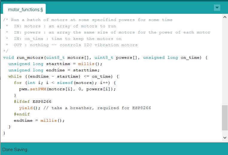
Figure 1. Shows the AI portion of the game code which is responsible for causing different Athenians to flock to the player within the game.


Is your progress on schedule or behind? If you are behind, what actions will be taken to catch up to the project schedule? 

Having encountered translation issues with the AI portion of the game code, I will need to invest some time this week to debugging my current code. This further risks delaying two main tasks namely, building the Node JS server and tracking the coordinates and game actions of the different enemies within the game. Since, listening for the game actions of different enemies is completely contingent upon the successful translation of the game code I will inevitably have to delay this task. On the other hand, I can start building the Node JS server while simultaneously debugging my translated code in order to mitigate severe delays from occurring in our schedule.


What deliverables do you hope to complete in the next week?

My deliverables are the same as those of last week with a few additions considering the issues I need to debug. Thus, I plan to finish transferring the game code from Javascript, HTML and CSS to Node JS as well as start tracking the coordinates and game actions of the different enemies within the game.  I also plan to build the Node JS server simultaneously with my other tasks. 

Amelia’s Status Report for 2/25

Updates for the week

This week, I mainly worked on configuring the Arduino Wifi Rev 2 to the same internet network on my laptop IDE. This was met with challenges, after 2+ hours, I could not get it to configure. At first I believed the issue was due to the fact that to connect to CMU-Secure, you need both a username (i.e. andrewID) and password which is a little tricky to configure on the Arduino. All the starter code assumes that the internet network is only protected by a password. To circumvent this, I connected my laptop to my phone’s wifi hotspot which only requires a password to join (not a username and password). When I tried connecting the Arduino to the wifi network, it wouldn’t connect. The figure below is the error message I was met with in the IDE’s serial monitor.

Figure 1

I also tried connecting with another phone’s hotspot and was met with a similar error message. I will continue researching ways to fix this next week.

In conjunction with testing the Arduino wifi rev 2, I also finalized my research on the haptic feedback locations on the torso. This was based on research from Pneumatic and acoustic suit: multimodal haptic suit for enhanced virtual reality simulation by Daeseok Kang, Chang-Gyu Lee, and Ohung Kwon published in Virtual Reality in 2023 and Whole-body mapping of spatial acuity for pain and touch by Mancini et al. published in Annals of Neurology in 2014. From Kang’s paper,  I took this mapping of motors shown below and noted where there was the smallest gap between the red and the grey dots for the same corresponding number. These are the most ideal spots to place a haptic feedback point since it’s where users most accurately detected the location of the motors used in this study. In figure 3, I isolate the most ideal spots to place a haptic feedback by placing them into individual blocks. The blocks signify that it is a single feedback point, i.e. motors in this spot are synchronized to work effectively as “one” motor

Figure 2


Figure 3

Based on Mancini’s paper, I got a good sense of where to place the motors on the shoulders of a person’s body, and together I placed the feedback points on a 3D model of a body as shown in figure 4. Together, there are 8 motor blocks on the back, 2 on each side, and 6 on the back. All the motor blocks have 2 motors inside, with the exception of the 2 motor blocks on the front torso, which have 4. One of these blocks will placed over the heart, which we could use to localize the low health algorithm (to stimulate an increased adrenaline rush different from all other points on the torso).  

Figure 4

Lastly, I worked on configuring the wireless Xbox controller we ordered for the game, and it worked seamlessly. I tested this out on a gamer who stated they didn’t have any problems while playing with the controller. Additionally, I had the gamer play at a distance well over 6ft and the connection was still maintained. This is 1 step towards our wireless experience. I don’t anticipate having to test the controller again until we have finished the motor/light integration on the vest itself.

Progress On Schedule

In terms of the schedule, I am very worried about the getting the connection set up on the Arduino wifi. I think I will have to do more testing + reach out to the TA in order to resolve this. If it can’t be resolved, we can always order the ESP32 board detailed in last week’s report. Other than that, I’m worried about getting the PCB design. I have no prior experience with PCB designing so I will have to do some Eagle tutorials while working on the previous tasks mentioned.

Deliverables for next week

For next week, I hope to have the Wifi connection with the arduino established so we can start testing the range and bandwidth. I also need to order RGB lights, for this I’m planning on ordering 8×32 RGB led matrix off Amazon, but need to check the specs (i.e. Arduino compatibility, voltage required to power, #of input pins required) before I commit to ordering. I also need to do some Eagle tutorials if we’re going to order a PCB before spring break. Lastly, I will work with my team to submit a project report before spring break.

Team’s Status Report for 2/25/2023

What are the most significant risks that could jeopardize the success of the project? How are these risks being managed? What contingency plans are ready?  

The most significant risks that could jeopardize the success of the project are getting the vibrations motors operational. This means we need to come up with a way for the current output from the servo driver to increase. The risks being managed are reassigning tasks to research either a solution to increase current from the PWM pin, or to create a custom PCB to accomplish the task. 

Were any changes made to the existing design of the system (requirements, block diagram, system spec, etc)? Why was this change necessary, what costs does the change incur, and how will these costs be mitigated going forward?  

Additions made to the existing system are adding an extra block between each servo driver output and a vibration motor. This was necessary to ensure the motors will have enough haptic feedback for the gamers to feel. This will increase the cost of the system. A fully custom PCB that connects to the Arduino I2C and outputs PWM on two pins would have been better, however with little experience with creating custom PCB, figuring out custom I2C communication protocols on the PCB may be a bit too much for a first project. 

Provide an updated schedule if changes have occurred. 

If the PCB is designed and sent out before Spring break, it can be tested when we get back.

This is also the place to put some photos of your progress or to brag about  component you got working.

We’ve finalized where on the body the motors should go. We also got our vest in and, despite it coming in a small size when we wanted a larger size, it will work perfectly for the haptic suit. We found that turning it inside out will allow the RGB lights to shine through the material.


Enumerate how you have adjusted your team work assignments to fill in gaps related to either new design challenges or team shortfalls (e.g. a team member missing a deadline).

We have adjusted the team work assignments by compressing some of our larger milestone projects (like programming a motor algorithm) to make space for getting a necessary custom PCB built. 

Sophia’s Status Report for 2/25/2023

What did you personally accomplish this week on the project? Give files or photos that demonstrate your progress. Prove to the reader that you put sufficient effort into the project over the course of the week (12+ hours).  

This week I focused on testing the Arduino to vibration motor system. After playing with the Adafruit GitHub code for the servo driver, I found a way to turn the vibration motors on and off. This was difficult because, as I found while testing, most of the servo driver examples weren’t configured to turn one output on and off, and they never turned on the output long enough for me to see the vibration motor in action. Creating the code and functions to turn the motor on and off led me to realize that I could not connect the motors in the same way I could when connecting them to an Arduino output. 

Figure 1: run motors function

This is because the Arduino supplies enough current (10-15 mA maybe, I forget at the movement and don’t have the parts with me) to make the motors vibrate and the necessary frequency for a solid feedback. However, the servo driver has the GND, V+, and PWM pins. While connecting the vibration motor provides enough current (~8 mA) to sufficiently turn the motor on, the PWM pins provide just current (~0.2 mA, I think) for a 3-wire PWM device to read the voltage level and convert that into how much voltage to draw from the V+ pin. With the vibration motor’s two pins and the PWM’s lack of sufficient current, a new solution is needed to drive the motors. 

Link to video of motor vibrating

Figure 2: the full system working (WordPress doesn’t like videos)

I have come up with a 2-path approach to solve the problem while limiting the impact to the schedule and our plan. The first path is to research how to either 1) drive a 2-wire PWM device from the 3-wire system, 2) “amp” up the current (I’m tired but check out my fun ECE pun…) of the PWM pin, or 3) create a custom PCB to accomplish the first research avenue if that avenue isn’t readily available. The second path is that while I am researching, I can also test and build up my code to run the motors. I don’t need the motors to work perfectly to see if I can properly create a class which can run specific waves of motors at a time for each unique haptic response. For the first path, a fully custom PCB that connects to the Arduino I2C and outputs PWM on two pins would be ideal and maybe I will try to design one if I have time at the end. However, I do not have the amount of experience necessary to design a communication protocol and do not want that to become a time drain when there is another way to accomplish my task.

Is your progress on schedule or behind? If you are behind, what actions will be taken to catch up to the project schedule?  

My progress was on schedule this week. I was successfully able to debug why the vibration motors weren’t turning on. From that, I also created some functions to turn on specific motors for a specified amount of time. For my future schedule, I will be a bit packed before spring break. I believe I will end up making the custom PCB so I need to alter my schedule to make time for that. 

What deliverables do you hope to complete in the next week?

I hope to design a PCB to either increase current from one input to an output, or design a PCB to do similar level checking as 3-pin PWM devices to output a correct current and voltage. 

Bethel’s Status Report 2/18/2023

What did you personally accomplish this week on the project? Give files or photos that demonstrate your progress. Prove to the reader that you put sufficient effort into the project over the course of the week (12+ hours). 

Progress from Last Week

My teammates and I successfully finished ordering all of the essential parts for our project and have created our design presentation slides.    

The more pressing tasks I had to complete over this past week included deciding between which idea to implement for tracking our game data and beginning to implement that method. Upon consulting with my team and Omkar we decided on implementing the method where we will be listening for each game event and casing on the actions that we wish to track (i.e. attack, forceful jump, getting hit and low health). 

Some game actions have been harder to track than others. For instance, it is hard to track low health as it would require listening in on all of the enemies’ game data, whereas it is much easier to listen for the user’s game attack actions. 

After gaining a better understanding of how we expect the game code to interface with the Node JS server, I realized that we should transfer all of the game code from Javascript to Node JS. I have accordingly revised Figure 1. below to accurately portray this relationship.  

Figure 1. Shows how the game software will use socket.io to relay information to the Node JS server. The server will then use the serial port package to send this information to our Arduino.


Is your progress on schedule or behind? If you are behind, what actions will be taken to catch up to the project schedule? 

Having discovered that I might have to translate all the game code from HTML, CSS and JavaScript to Node JS, I will be dedicating the beginning of this week to accomplishing this. After successfully achieving this, I will move on to listening to the game events of different sized enemies within The Last Spartan. My schedule for this week is thankfully flexible enough to accommodate these unforeseen changes.    


What deliverables do you hope to complete in the next week?

I plan to finish transferring the game code from Javascript, HTML and CSS to Node JS as well as start tracking the coordinates and game actions of the different enemies within the game.  


Please list the particular ECE courses (if any) that covered the engineering science and mathematics principles your team used to develop your design? If there are no courses please tells us how you learned those principles over the last week?

I primarily utilized principles from 18213 Introduction to Computer Systems in understanding the design of our Node JS server. I particularly referred to the knowledge I gained from implementing Proxy Lab, which utilized sockets. I similarly plan to use sockets in sending data from our desktop game to the Arduino. By understanding how to implement these sockets and use the http library I have been able to create event listeners that are compatible with the Node JS server.


Amelia’s Status Report 2/18

Updates for the week

This week I tested the vibration of the coin motor using an Arduino in order to get a sense of how strong it felt to the human touch. At first, I programmed it using a digital pin which can only be programmed to either high (highest vibration  strength) or low (off). I found this created an extremely unpleasant sensation, the motor did not need to be at maximum strength. Instead, I programmed it using an Analog pin (known as a PWM pin on an Arduino) and set it to half strength which sits at about 127 on a scale of 0-255. The simple code I wrote for this test can be found in our Github, under the “arduino-testing” repository

Next I researched how to get more PWM pins on an Arduino. An Arduino only carries 6 PWM pins, and for our implementation, we’re going to need around 20 pins. This meant I need to either convert the digital pins to PWM pins or look for a hardware alternative. I went with the former solution seeing as we already have several Arduinos on hand to test and waiting for another piece of hardware was not going to effective. This brought me to use the softPWM library available on the Arduino IDE, which is capable of converting digital pins to PWM pins.

I also researched the possible avenue of a joystick with an accelerometer as an input device in order to remove the keyboard from the gaming experience. As mentioned in the team status report, we had to abandon this idea based on our user survey.  Users stated this type of control is very unpopular, and going out of style in the gaming community. Thus, our team is advancing with the wireless Xbox controller idea and I used my time this week to reconfigure the keys of an existing Nintendo controller I had, to keyboard keys. I reconfigured the keys through a gaming platform called steam as shown in figure below. I had to be thoughtful about where exactly to map the keys, this required me to think about where a person’s thumb naturally lies when holding a controller (this should correspond to a <space> hit on the keyboard), what keys are they most likely to hit during the game (jump and attack) and where I could map those on the controller. I used my own Nintendo controller for this test, but since it only has a wire capability, we are going to order an Xbox controller for the final project design and the logic still stays the same.

figure 1


I also needed to ensure that the suit remains wireless. To do so, the Arduino inside the vest which connects all the motors and RGB lights together, needs to be wireless as well. Since we don’t have any input sensors in our suit, it only needs to act as a receiver and our laptop which holds actual parsed user game data, will act as a transmitter.  I landed on two possible solutions to achieve this: (1) using a regular Arduino but attaching a Wi-Fi shield. This required us to buy a $69 XBee antenna and it doesn’t have SDA/SCL pins we would need in order to expand our pin range and use I2C. (2) using an Arduino Wi-Fi Rev 2. This solution requires us to buy an expensive Arduino ($53) but it works perfectly as long as we connect the Arduino to the same Wi-Fi as the Wi-Fi on the transmitting laptop. (3) Using an ESP 32 board. It’s fairly priced ($13.99 for two boards) but I didn’t explore this solution too much. It was brought forward by our team’s TA after we ordered the Wi-Fi Rev 2 but if the Rev doesn’t work, we will definitely have this to work with.

Progress on Schedule

So far, I’m on schedule so that we can begin simple integration tests over the course of next week, but I will need at least some time to myself in order to test the wifi rev 2 before we can do effective integration testing.

Deliverables for next week

I’m currently still researching what points on the torso will feel . I landed on a research article that gave a good point for the shoulders, but I need more for the front and side torso. I think over the course of the next week, I will finalize these feedback points by reading more research articles and map them in order to move forward. I will also look more into how we want to package the motors for each feedback point, exploring a PCB board as an option since it is easy to reproduce and scale.

ECE Courses

I think the most useful ECE courses that cover our design principles would be 18300 (getting the motors and sensations correctly) and 18213 (general coding abilities). Relating to Arduino and sensor knowledge, 60225 (intro to physical computing) helped immensely since we were working on bringing projects with input devices to life using Arduino.

Team Status Report 2/18

Current Project Risks

Currently, the most significant risks that could jeopardize the success of the project revolves around our individual tasks. While we may find challenges within our individual tasks, those will be covered by our personal status reports. The main risks are: Sophia figuring out how to drive 2-wire vibration motors with the 3-wire PWM pins, Bethel tracking the actions and coordinates of the enemies within The Last Spartan game, and Amelia with pinpointing where to package the vibration motors in the vest that corresponds with existing spatial acuity data. To manage these risks, each member will focus on fitting their part. Sophia will stagger between testing the motors and determining if a PCB board could be configured to convert the necessary power. Amelia will continue reading existing research on vibrotactile stimuli on the torso as well as making sure the Arduino Wifi Uno is able to receive information seamlessly without noise interruption. Bethel will identify the event handlers dedicated towards different types of enemies within the game.  

We also foresee integration as a possible risk. To mitigate this, we plan to do basic integration tests next week. These tests will include sending data from NodeJS server to Arduino and packaging a single coin motor in the vest to ensure it does not move beyond our constraint of 1” radially once on.

Changes to Existing Design

We’ve been thinking about how we could make the experience of a haptic suit more seamless, namely with a keyboard-free experience. Our first idea was to build a joystick input device with an accelerometer that a user could use to swing vertically up and down in order to “attack” enemies in the game. After surveying various gamers and doing our due-diligence with our own research, we found that this type of input is called a “waggle controller”. The waggle controller was popularized by Ninetendo in the early 2000s, being a common feature in games such as Wii Sports, Super Mario Galaxy, Donkey Kong Country Returns, The Legend of Zelda: Twilight Princess, and Rayman: Raving Rabbids. It’s highly unpopular amongst gamers because of the general “lack of skill” it requires out of the user, only random movements to get it to work. Instead, we will be using a wireless xbox controller that a user can use to control their in-game actions. This is the most popular and well-known type of controller because of its ease of use and affordability, running around $50 for a wireless option. We will be mapping the keys on the controller to the keys on the keyboard using the platform “Steam”. We will also be changing the in-game instruction graphics to reflect the controller being the input device instead of the keyboard. 

We also spent a lot of time thinking about our design implementation block diagram. This helped us understand the interdependencies of our tasks. This will allow us to move forward with our parallel tasks knowing what has to be done to integrate the system.

As we’ve proven, moving forward, the best way to vet our design and implementation changes is to survey our users. Ask them what they want in order to improve their experience. Being that we are not gamers ourselves, we aren’t reflective of a typical user and thus can’t speak to what they would like. We can only implement changes and bring the system to life. 

Principles of Engineering Utilized in Project

We utilized multiple principles of engineering, science and mathematics to develop our design solution including I2C protocol, server design, researching spatial acuity in the body, event handling in JavaScript and Circuit design using an Arduino.  

We are employing the engineering design process in every aspect of our project. We have focused on ensuring our project is very modular with lots of parallel tasks which can be completed by our group simultaneously. We are currently working on the research and prototyping phases of the engineering design process.


Sophia’s Status Report for 2/18/2023

Accomplishments this week:

Last week I planned to focus on creating the motor control algorithm due to the uncertainty of getting parts in. On Monday, along with working on our block diagrams and user survey on our physical input system, I worked on my motor control algorithm. This included looking into how the Adafruit I2C device would control the outputs and also how to create classes in Arduino. Amelia was able to test a vibration motor with the Arduino and found it worked with the Arduino’s PWM pin with sufficient vibrational feedback. Testing the motors further would have to wait for the servo driver.

Algorithm: The main issue I found with creating the Response class in Arduino is that I need to come up with a way to make variable sized arrays. The arrays will hold which motors I want to activate for each “wave” of a haptic response. I figure I can either initialize longer arrays that I’ll need then be required to fill with -1’s for the unused indexes, or I can create some sort of variable length char array. Hardcoding various haptic patterns is also an option, but I’d like to make something more variable. However, for initial testing purposes, hardcoding to ensure the variable sized array isn’t causing a bug might be a good starting point. This left me at a point where I would have to know more about the I2C device to successfully use the functions. 

Figure 1: algorithm idea that needs knowledge about I2C controls

Soldering and I2C: Thankfully and unexpectedly, the I2C servo driver and the motors came in on Tuesday. This allowed me to spend Wednesday relearning how to solder so I could solder the header pins onto the servo driver PCB. This, along with doing some tasks with my team,  took most of the class. I ended up finishing the soldering on Friday. I then proceeded to test the vibration motors when they are connected to the I2C device. I did come across some minor issues using the I2C device: the motors don’t seem to run. I used my good old 18-100 debugging circuit skills to try to figure out what was going wrong. The device is set up so there are the GND, SLC, SDA, and VCC pins coming in from the Arduino which provide the signals for the device. Then there is a V+ pin which is connected to a different 5V power supply to supply voltage to the motors. I was able to wire up the I2C device so when I run code to turn on and off an output, you can measure the changing voltage with a multimeter. And I also had some basic servo motors from 18-100 which did move when the code was run. However, the small vibration motors–despite me being able to read a voltage up to 5V from the PWM to GND pins–did not buzz. 

Figure 2: the I2C servo driver PCB board with header pins
Figure 3: simple I2C device setup from Arduino to I2C to vibration motor

Other Stuff: I also worked with Amelia and Bethel on our Design Report presentation.  (Saturday night update: a lot. We worked on the design report presentation a lot). The design report required multiple schematics and wiring diagrams that took a while to design. 

Updates on my schedule:

I am currently on schedule. With the change with the physical input device, my schedule has changed a bit, but my two main tasks of creating the motor algorithm and driving the motors from the servo driver are still on schedule. Although I am going to switch up my schedule because I want to get the motors working properly before moving forward with the algorithm. I believe this will allow me to better understand what functions and parameters the algorithm needs to control.

Deliverables for next week:

Next week is pretty busy for me in most of my classes, but I plan to have some basic working code so specific motors can be signaled to turn on and off given some power and time_on values. This requires me to debug why the power I’m providing to the motors does not cause them to vibrate. Once I have basic function to run one motor, I can easily add them to an class function in Arduino so I can run multiple motors at the same time and in a specific pattern.

List the particular ECE courses (if any) that covered the engineering science and mathematics principles your team used to develop your design

I used 18-100 and 18-220 for the principles on how to set up I2C connections and debug circuits. These classes allowed me to design my system so the ground from the I2C power source was connected to the ground of the Arduino. This is required so they are in the same circuit and weird different-circuit errors don’t occur. I also believe 18-100 had a soldering lesson freshman year so that helped me with soldering the header pins onto the servo drive PCB this week.  I’m also using 15-112 principles for designing my algorithm and creating a class in C++. I think the reason I’m using all my freshman year courses is because it is in those classes I learned the basics of engineering which can be generalized a lot easier than later courses. A lot of my later courses allowed me to improve upon those generalized skills while specializing in other areas. However, most of those specialized skills may not come into play with this project, hence the focus on earlier classes.


Amelia’s Status Report 2/11

Updates for the week: 

This week, I worked on researching the best motors to provide a haptic feedback. I landed on two types of motors: pager motors and mini vibration motors. Each of the motors comes with drawbacks and advantages, with the advantage of the mini vibration motor being it’s small and has compact shape that will minimize the weight of the vest. The pager motor will be more difficult to mount to the vest because of its boxy shape, so I believe we are going to go with the mini vibration motors.

I also spent some time prototyping the design of how the motors will function inside the vest. Since the mini-vibration motors are smaller than the size of a quarter (10mm diameter), my initial thought is to arrange 4 motors into a “flower” that will function as a single feedback point. To mount this, I will laser cut a chip made out of acrylic that can support the 4 motors in a pattern (as shown in Figure 1). In order to actually get the chip into the vest, I thought of a method to get a thin, expandable material (i.e. spandex) which we could sew into the inside lining of the vest itself. We would create a “pocket” of sorts with this material in which we could take the motor chip in and out of + connect to common ground/power + connect to the STM which would rest in the back of the vest.

figure 1

Lastly, I did some research into the best RGB lights for the haptic suit, and landed on the neopixel ring light. This was best suited for our project since it will outline where there is haptic feedback point is on the vest, and is easily adaptable to an Arduino (there is a corresponding neopixel library that we can download).

Progress on Schedule:

We’re still on schedule, but need to work diligently this next week since we spent a lot of time researching. I think the biggest roadblock right now might be getting the parts in order to test them. I have a mini vibration motor in my own personal Arduino kit, so I can test and approximate if 1 motor per haptic point is enough, or we really do need 4. Once we get more motors, this will be easier to determine.

Deliverables for next week:

Over the next week, I hope to test the motor pattern and determine if it simulates a feedback that corresponds to the game and doesn’t deter from the experience. I will also determine if its too many/not enough motors or if the motor needs to be changed for a specific point (i.e. maybe the motor over the heart needs to be stronger than the rest to simulate a thumping sensation). If the motor chip design works well, I will then work on creating a “motor chip flower” class in the Arduino IDE in order to modularize the system since we will be working with a lot of motors, and they all need to be synchronized. When an instance of this motor class is called, it will activate the motor flower chip as one, so that it seems like you are controlling only one motor while hiding the fact that it is actually 4.


Bethel’s Status Report for 2/11/2023

What did you personally accomplish this week on the project? Give files or photos that demonstrate your progress. Prove to the reader that you put sufficient effort into the project over the course of the week (12+ hours). 

I spent the majority of this week researching different ways of tracking the actions of players, reading cognitive psychology papers on what types of motors improve the immersiveness of games and inspecting different motors and vests to add to our parts list.

Prior to presenting my team’s proposal, I asked my cognitive psychology professor to recommend some papers to me that evaluate the effectiveness of haptic suits in providing realistic physical feedback. I was interested in understanding the types of motors that these suits utilized and determined that vibrating motors will be the most appropriate type motor to use as opposed to thermal pads that heat up different body parts of the user and or the combination of both vibrating motors and thermal pads. 

The readings helped inform me on the types of vibrating motors we should include within our parts list. These motors were scrutinized on the basis of their rotations per minute (RPM), size and price. Moreover, I also researched different (non-haptic) vests that will fulfill our users’ comfortability, sizeability and safety needs. My teammates and I reached a consensus on purchasing a “bulletproof” style vest that fits all of our criteria, while also being aesthetically pleasing (as shown in Figure 2). 

I also cloned “The Last Spartan” repository and evaluated different ways of approaching how the player’s game data should be tracked. I narrowed down the approaches to accomplishing this as the following:  

  • Console logging the output of certain gamer actions such as attack, forceful jump, getting hit and low health
  • Listening for each game event and casing on the actions that we wish to track (i.e. attack, forceful jump, getting hit and low health)

The decision on which method is better will be primarily contingent upon how we intend our Node JS server to interface with the game software (Figure 1 shows this simple relationship).


Figure 1. Shows how the game software will use socket.io to relay information to the Node JS server. The server will then use the serial port package to send this information to our Arduino.


Is your progress on schedule or behind? If you are behind, what actions will be taken to catch up to the project schedule? 

We had planned to put our orders in for parts this week, however this plan has been delayed by a few days. These delays will affect my collaborators more than it will affect my contributions to our project, because my role within the team primarily focuses on our software solutions. 


What deliverables do you hope to complete in the next week?

I plan to finish ordering our parts and help my team make the design presentation slides. The more pressing tasks I have to complete this upcoming week include deciding between which idea to implement for tracking our game data and then beginning to implement that method.

Figure 2. Shows the vest we plan to purchase