What did you personally accomplish this week on the project? Give files or photos that demonstrate your progress. Prove to the reader that you put sufficient effort into the project over the course of the week (12+ hours).
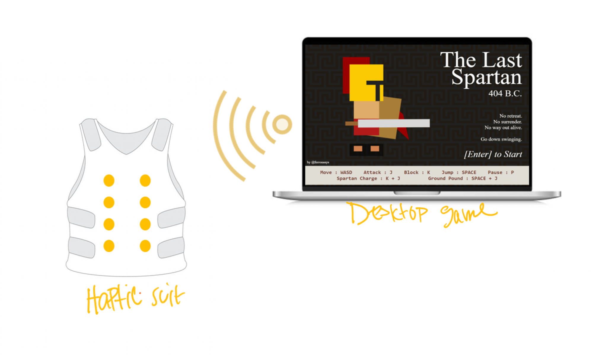
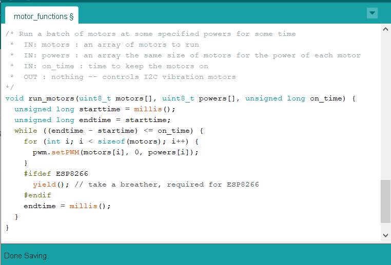
This week I focused on testing the Arduino to vibration motor system. After playing with the Adafruit GitHub code for the servo driver, I found a way to turn the vibration motors on and off. This was difficult because, as I found while testing, most of the servo driver examples weren’t configured to turn one output on and off, and they never turned on the output long enough for me to see the vibration motor in action. Creating the code and functions to turn the motor on and off led me to realize that I could not connect the motors in the same way I could when connecting them to an Arduino output.
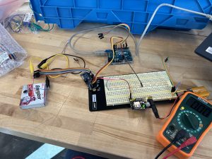
This is because the Arduino supplies enough current (10-15 mA maybe, I forget at the movement and don’t have the parts with me) to make the motors vibrate and the necessary frequency for a solid feedback. However, the servo driver has the GND, V+, and PWM pins. While connecting the vibration motor provides enough current (~8 mA) to sufficiently turn the motor on, the PWM pins provide just current (~0.2 mA, I think) for a 3-wire PWM device to read the voltage level and convert that into how much voltage to draw from the V+ pin. With the vibration motor’s two pins and the PWM’s lack of sufficient current, a new solution is needed to drive the motors.
Link to video of motor vibrating
I have come up with a 2-path approach to solve the problem while limiting the impact to the schedule and our plan. The first path is to research how to either 1) drive a 2-wire PWM device from the 3-wire system, 2) “amp” up the current (I’m tired but check out my fun ECE pun…) of the PWM pin, or 3) create a custom PCB to accomplish the first research avenue if that avenue isn’t readily available. The second path is that while I am researching, I can also test and build up my code to run the motors. I don’t need the motors to work perfectly to see if I can properly create a class which can run specific waves of motors at a time for each unique haptic response. For the first path, a fully custom PCB that connects to the Arduino I2C and outputs PWM on two pins would be ideal and maybe I will try to design one if I have time at the end. However, I do not have the amount of experience necessary to design a communication protocol and do not want that to become a time drain when there is another way to accomplish my task.
Is your progress on schedule or behind? If you are behind, what actions will be taken to catch up to the project schedule?
My progress was on schedule this week. I was successfully able to debug why the vibration motors weren’t turning on. From that, I also created some functions to turn on specific motors for a specified amount of time. For my future schedule, I will be a bit packed before spring break. I believe I will end up making the custom PCB so I need to alter my schedule to make time for that.
What deliverables do you hope to complete in the next week?
I hope to design a PCB to either increase current from one input to an output, or design a PCB to do similar level checking as 3-pin PWM devices to output a correct current and voltage.