This week, I switched over to using a new library for the light algorithm. The previous Adafruit library was not capable of running the code I needed at the right speed, and included delays which disrupted several other functions. I switched over to the “FastLED” library, which allows me to use non-blocking delay code, which is a step towards parallelization with the motors and lights. A video of me running different patterns can be seen here.
I also rehearsed for our final presentation on Monday and am continuing to work with our team to test the threading code, solder 3 more PCBs for the back motor integrations, and wrap up our poster in time for the Techspark demo.
Progress On Schedule
We’re behind on schedule. We said we’d finalize everything by the end of this week, but this got pushed back so I will simultaneously continue working on my parts while not neglecting my final exams.
Deliverables for next week
Finalize the parallelization code so that the motors and lights go off at the same time, finalize the light pattern for hit small and hit large, and soldering + test the remaining 3 PCBs.
I got the serial monitor to read the incoming bytes from the nodeJS and parse the data into a struct so that all functions can access this data. The relevant data is: action type, health level, and desired motor intensity. I worked on this integration with Bethel and tested playing the game to see if each relevant action would correspond to a unique light response, and it did which meant we could test the delay.
Afterwards, I integrated this code w with the light and motor control code and began testing it outside the vest. It worked then, but unfortunately, after we placed it inside the vest it didn’t work. There were some code changes when w placed it inside the vest so it could either be a wiring or software issue.
Aside from these primary tasks, I’ve also been laser cutting more boxes so that the wire systems do not come loose from the i2c or buck converter, helping strip/crimp the motors, and doing general integration with my team.
Progress On Schedule
The primary risk as of now involves the light and the motor timings, I realized that they are not occurring at the same time so I need to incorporate threads into the code so that it appears as though they are occurring at the same time. Of course, the user won’t see the lights, but this is to ensure that there is synchronization and the timings isn’t skewing off other queued up actions.
Unfortunately, Bethel and I couldn’t get wireless communication between the nodeJS and the wifiRev, so for the sake of time and completing integration, we decided to hold off on this until after MVP. We understand this means we will not pass one of our design requirements, but felt it was more important to have a finished product rather than a half complete system.
With this, I’m slightly off schedule as integration meant we discovered new problems that need to be addressed urgently. I hope to get back on schedule before finals week.
Deliverables for next week
As Gary noted, the vest light should incorporate some animations, so I’m working on animations for the getting hit action while also integrating with the team. I’m hoping this animation will be in the form of a random pixel turning on and the k pixels near it blurring until they turn off.
Moreover, the delay between each game action is extremely small, so I need to update the timing of the lights so that the corresponding light action has ample time to display, and isn’t just gone in a flash. This requires some tuning and playing around with the numbers till we get a delay that isn’t too small or too large. As mentioned above, I will also be incorporating threads into the integration code.
Finally, I will work with my team to finish the final powerpoint, and poster for the upcoming week’s deadlines.
This week, I focused on laser cutting the motor mounts, arduino case, and pocket squares as well as working with Bethel to get communication between nodejs and the WIFI rev.
I laser cut the motor mounts out of the rubber sheet I demonstrated last week, only now they have holes aligned with the PCB holes so that we can fasten the mounting plate to the PCB. I also fixed the tolerance of the Arduino case lid, and used fabric to laser cut 20 pocket squares to the same dimension.
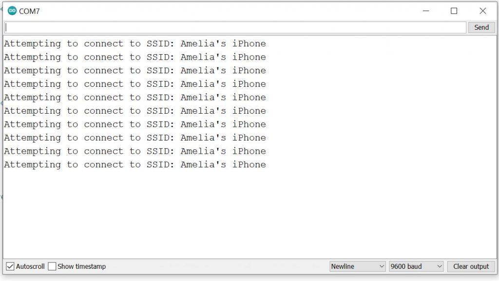
I spent the bulk of my time this week working with Bethel. At first we tried sending an HTTP post request to the WIFI rev, and after several tries we were able to see the correct request message. An image of the serial monitor can be seen here. We sent “ANYTHINGGG: KJNGDFGKJD”. The only problem with this was that it wasn’t synchronized to the game event actions. When we played the game on the website, it wasn’t transmitting any sort of data to the WIFI rev. From here, we switched tactics and opened a socket connection which was synchronized to the game, it sent data at a good frequency (which we will time later since at this point we are only concerned that we receive the correct data) but it doesn’t send the game data we want (i.e. ‘F’ for jump or ‘0’ otherwise). An image of the serial monitor output from this method can be seen here.
Progress On Schedule
So far I’m on schedule, but with about ~3 weeks left, I understand that if we can’t get the wireless communication to work, then we have to revert to the wired solution. This is so that we don’t fall behind on testing and validation.
Testing Plan
The deliverables I’ve been testing so far have been the wireless range and seeing if the Arduino IDE receives nodeJS response. To test the wireless range of both the Arduino and the controller, I just moved 6+ ft away from the laptop to see if I could still see a response/play the game. Both of these currently work.
The Arduino IDE is receiving a nodeJS response, just not the one we want so that test has been forthcoming. Once this works, I’m planning on printing the time between each of the responses in the Arduino IDE and computer running the nodeJS. I will take the difference to see how long it takes for the Arduino to receive a response once it’s sent and see if it meets our latency requirements from the game to the Arduino IDE. Afterwards, we will measure how long it takes the Arduino to send the response to the motor/light systems.
Deliverables for next week
Continue working with Bethel on getting the relevant game data to the wifi rev before the end of the week.
Crimp the motor systems so that they are able to be plugged into the PCBs
Synchronize the timing of my forceful jump light algorithm with sophia’s forceful jump motor algorithm.
This week, I focused on perfecting the forceful jump and low health light algorithm, the code for this can be found on our Github. A video of it can be seen here.
I also worked on ensuring that the lights had their own power supply since each LED draws a significant amount of current (20mA), and there was a common ground between them. My schematic for this can be seen here. I used a 6V power supply and used multimeter to measure the output voltage after this connection, which was ~5.12V. The rating for the lights is max 5V so for the final, I will use buck converter in order to get exactly 5V from 9V.
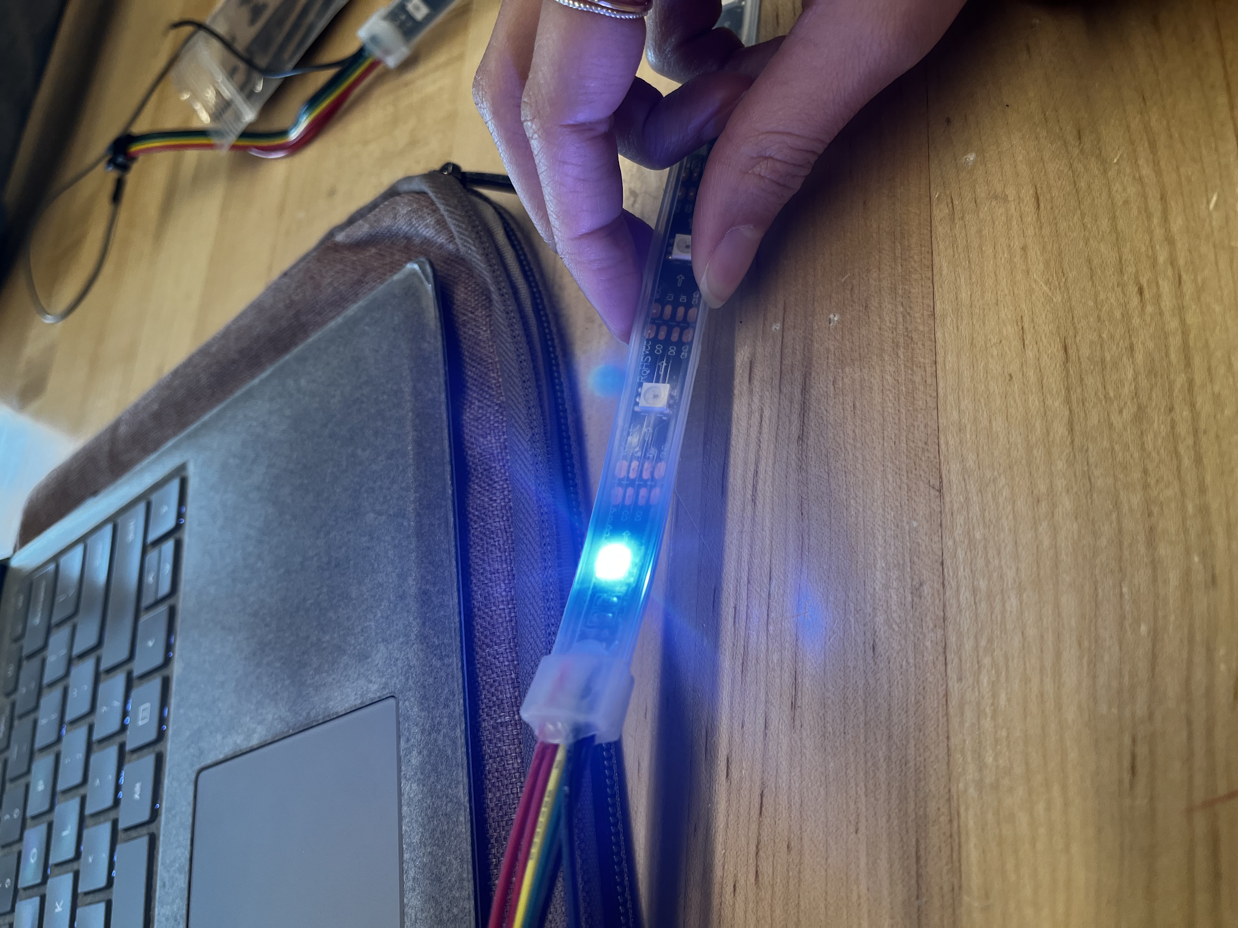
I also tested that the lights are able to be controlled wirelessly, which can be seen here.
I then laser cut 5 sets motor mounting plates out of cardboard since it is easy to prototype and we do not have the PCBs yet in order to use the rubber material I demonstrated last week. These plates will be only be used for prototyping and for the demo on Wednesday.
Lastly, I worked with my team to mount + wire all the motors to their mounting plate in order to fit them onto the vest properly.
Progress On Schedule
So far I’m on schedule, it became clear that there needs to be a lot of wiring management and tiny fixes for our final design. For instance, we only noticed today while integrating the motors to the mounting plate that I need to fix the CAD model for the motor mount slightly, they should be rotated 90 degrees so that the wires don’t break off as easily. I also need to continue working on integrating the wireless code with Bethel.
Deliverables for next week
I need to laser cut a box out of 3mm acrylic to hold the two battery supply systems
laser cut another box for the Arduino itself so that the wires connected to the Arduino pins don’t come lose and detach.
Continue working on getting the JSON data from bethel and parsing it so that the vest works wirelessly with the game data.
This week, I worked on getting the RGB lights (Adafruit DotStrips) to turn on in a specific pattern, placing them inside the vest, laser cutting the motor mounting plate, integrating the wifi REV with Bethel, and integrating the light system wiring to the vest with my entire team.
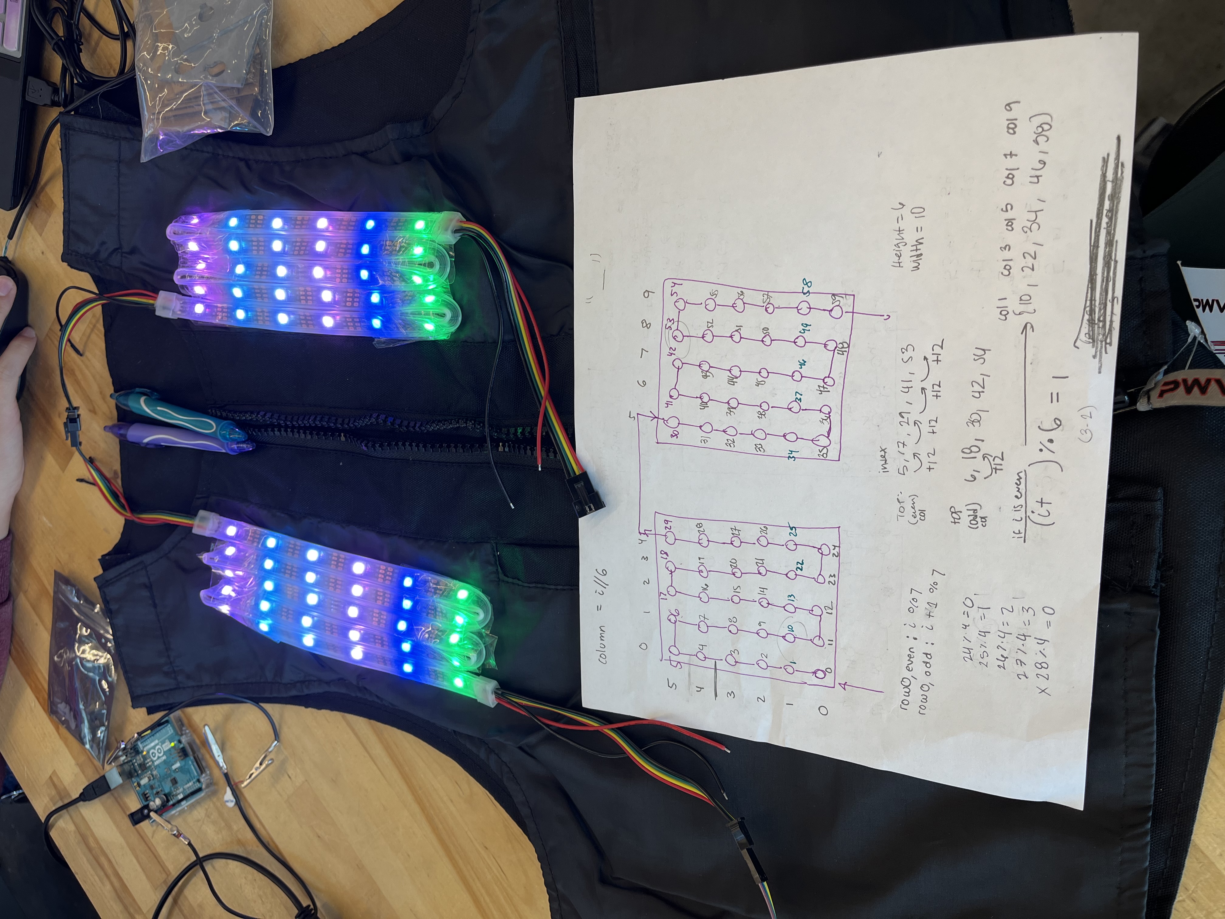
To turn on the lights, I used the Adafruit_DotStar library on the Arduino IDE and connected the datapin to 4, clockpin to 5, power to Vin, and ground to GND on the Arduino. Next, I set the all the LEDs’ red channel to high. From there I did a simple flashing motion to simulate a “low health” event. The low health light show only turns on when a user is below 25% health. As the user’s health decreases from this threshold, the faster it will flash red until the user dies, upon which the LEDs will stay red. For the forceful light response, we will have a cascading wave moving up then down to showcase this event occurred. I isolated the light indexes into rows/cols and which can be shown in the figure below (60 LEDs, 30 on the left and 30 on the right).
Figure 1: Light system on, separated by rows
Next, I worked on de-threading the bottom of the vest so that I could put the LEDs inside the lining of the vest and see how they shine. A video of this can be seen here. Since the lights need to be accessible to me (so that I could move them in/out of the vest as need), this meant that I also need a way to open and close the part of the vest I just de-threaded. For this, I placed Velcro strips on the inside lining that I could just pull/push together in order to open/close. I found this made the design still look seamless, and I could apply this solution to securing the light/motor systems to the vest, rendering my “pocket” solution I brainstormed in earlier weeks obsolete.
I also began experimenting with a different material for the motor mounting plate. I landed on rubber since it is cheap and flexible. I worked on laser cutting the .dxf file I made last week on this material, and the output of that can be seen in Figure X and X+1. I added additional space to the right of the motor holes so that we can place the PCB once it’s ready.
Figure 2: Motor mounting plate
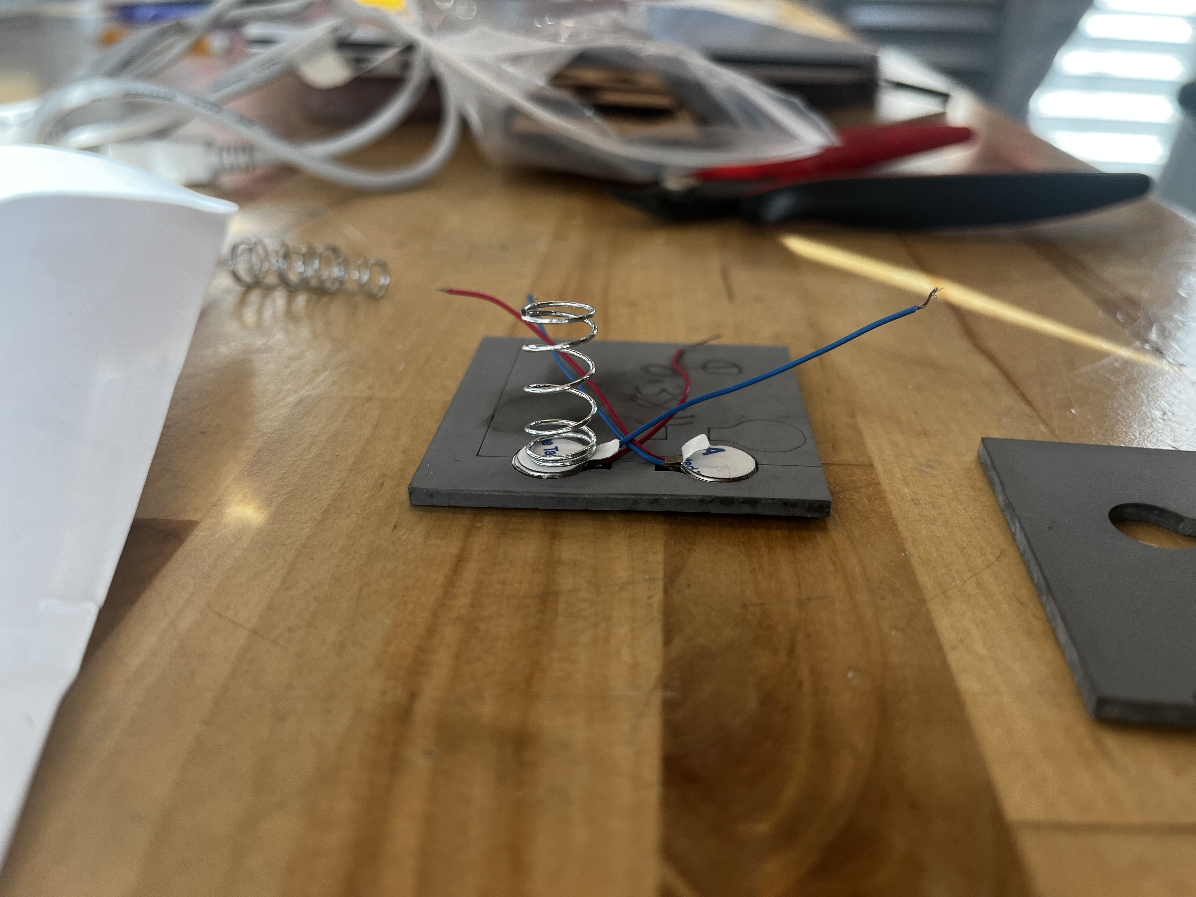
Eventually, the motors will have a spring attached to the back that will make sure there is contact with the motors and the torso of the user, regardless of their size. A rough idea of it is shown in the figure below.
Figure 3: Coin motor with a spring attached
Lastly, I worked with Bethel this week to ensure her part of the project was working with the Arduino Wifi Rev. We worked together so that she didn’t have to repeat any code that’s already written and so that we are able to see if the Arduino is able to receive a simple JSON message (“1” or “0”) she is sending. We were able to see the message, but need to work on sending more information-rich messages that explain an event like forceful jump, low health, getting hit by a small enemy, etc. etc. that are relevant for motor and light responses. After talking it through, we decided the simplest message that the JSON could send are 2, 1-hot vectors since her event precedence algorithm will mean that only one event is registered at a time .This moves away, but has the same essence of the message I worked on parsing last week.
Progress On Schedule
I’m still on schedule, especially now that I’ve gotten the light system up and working. I have also been integrating more with my team, which is a good sign as interim demo is coming up in the next two weeks.
Deliverables for next week
Next week, I plan on finalizing the forceful jump and low health light show timings with Sophia’s motor responses for the same events. The idea is that they last about the same amount of time with their respective motor event.
I will also continue working with Bethel to ensure the Wifi Rev is responding to her message wirelessly and with minimal latency that is within our design requirements.
I will also laser cut a set of motor mounts using cardboard to have ready for the interim demo. If the PCB arrives before Thursday, I will laser cut the mounts using the rubber material.
This week, I focused on parsing the POST request data from POSTMAN. I got this to work successfully, but after consulting with my teammates Bethel and Sophia about what the incoming data is going to look like, I realized that parsing data from POSTMAN is not the same as parsing data from JSON, but we agreed that any incoming data will have the string format “? MA, LA”
Where MA is a string that holds any of the 5 string values: ” “, “FJ”, “HS”, “HL”, “LH” corresponding to a motor action (i.e. FJ->Forceful Jump, HS->Hit Small, HL->Hit Large, LH->Low Health). LA holds similar 5 values: ” “, “W”, ” HS”, “HL”, “W” which corresponds to a light show action (i.e. W-> character in water).
I will parse this string format and hold the corresponding values in a struct so that the motor and light algorithms are able to case on these value instantly and send the correct response to the motors/lights.
These will start with a ‘?’ to let the IDE know we’re receiving the proper data.
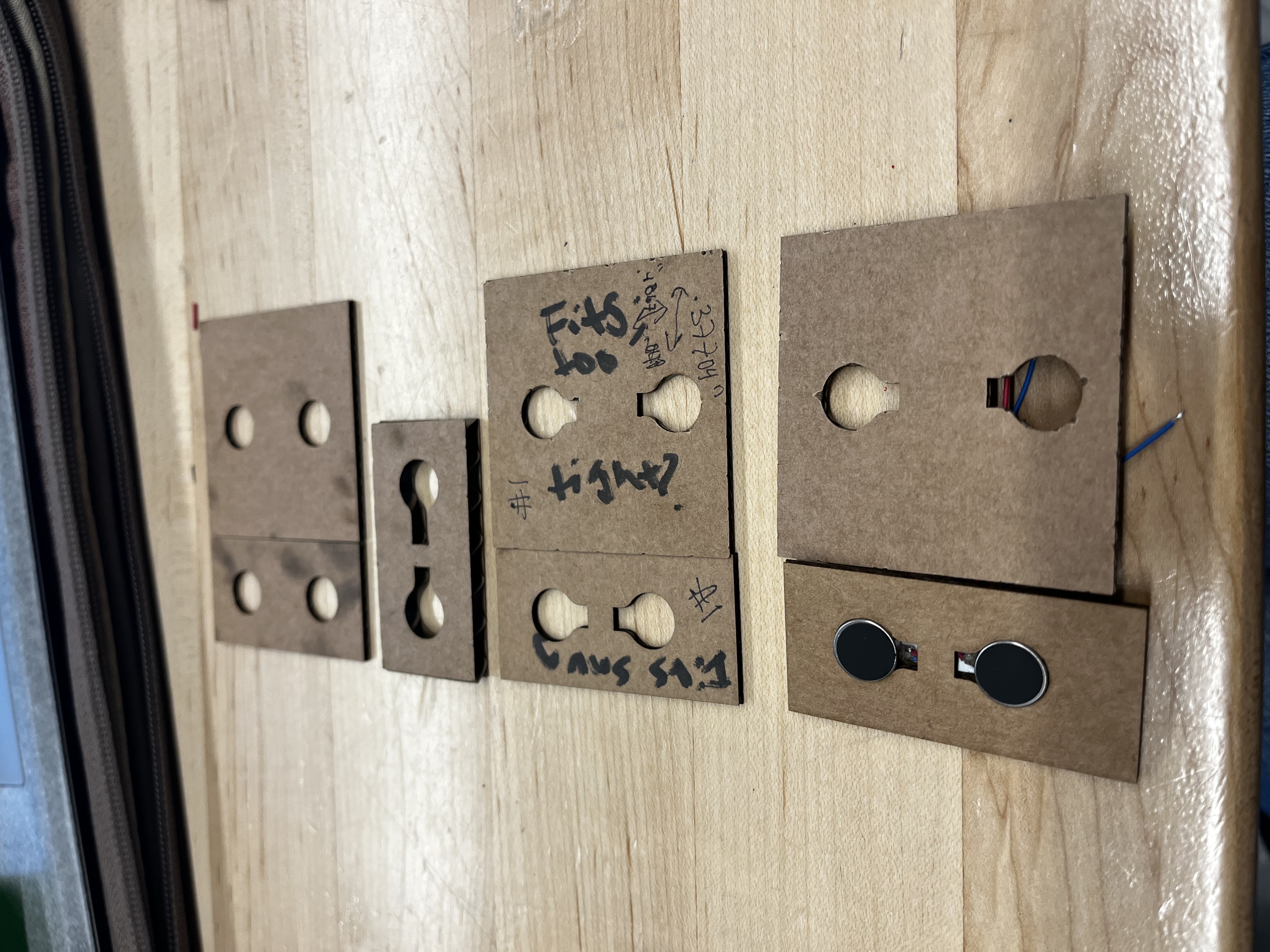
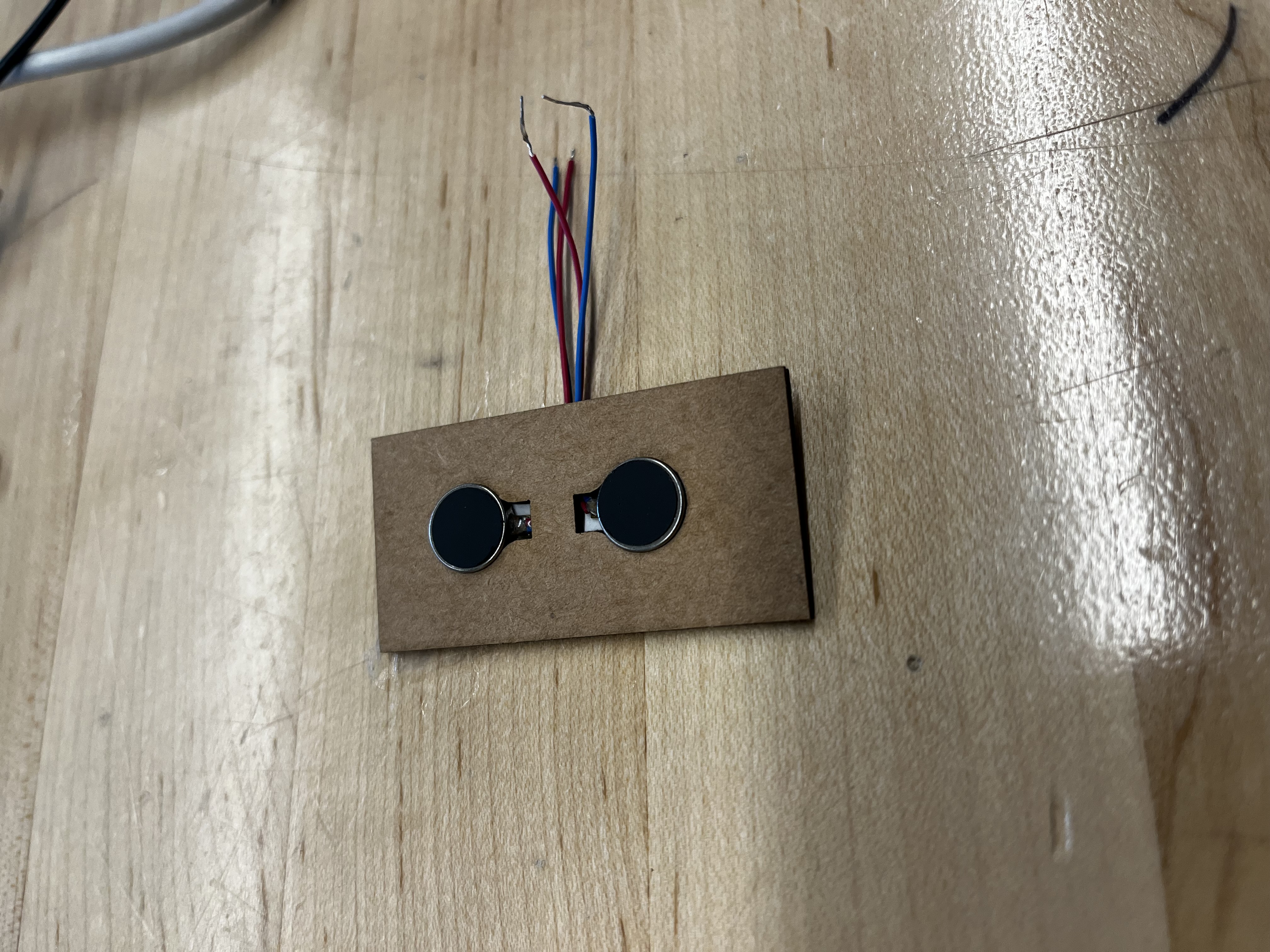
Next, I worked on prototyping the actuator mounting board. I started by creating a CAD model with squares and added 2 mounting holes 10mm in diameter to these squares. I laser cut them on (1/32)” cardboard then realized the motor surfaces weren’t flush with the cardboard because they didn’t have a notch for the wires in sticking out of the motors. I then added a notch on CAD and did several iterations of prototyping on cardboard. I laser cut on slightly thicker cardboard but the motor just fell out because the gap couldn’t support the motor, then went back to prototyping on (1/32)” thick cardboard. The image below shows the iterating process. I finally landed on a design which has holes 9.7mm in diameter (slightly smaller to ensure the motor doesn’t fall out) and a gap of 5mm between the two motors. I also tested these at half/full power and it wasn’t unpleasant at 5 mm apart, and did not fall out of the mounting hole.
I also worked on setting up the RGB lights. I turned on 1 LED but need to spend more time on it in order to have the Low Health light show functional as I stated in last week’s status report.
Progress On Schedule
Since I am no longer designing the PCB board, I only have to focus on getting the lights working, the motor mounting plate finalized, and Arduino working wirelessly. I have the Arduino working wirelessly already, it’s just a matter of parsing data from JSON, not from POSTMAN. I’m behind on getting the light algorithm working, so I will spend tomorrow (3/19) working on it.
Deliverables for next week
For the final motor placements, I’m intending on using a different, more durable material. I’m hoping to finalize choosing which material this is going to be, I’m in-between acrylic or a silicone sheet because of its lightweight and heat resistance. I plan on talking with the professor more about the pros/cons of each material.
Once Sophia has the finished dimension for the PCB, I plan on editing the CAD model to make space for the PCB on the actuator mounting board and laser cutting 8 of these to have them ready for the interim demo. The idea is that these 8 will go on the front of the vest, and I will make a plan to mount + wire them on the vest so that they do not move.
I will also get the low health light show algorithm working by the end of the week, so that we are in good standing to have at least one action completely done before the interim demo.
I got the Arduino working wirelessly. To work around the wifi issue I had last week, I connected the Arduino to the “CMU-Device” network and registered its MAC address on CMU’s device registration website. I also tested the range at which it could receive data and it worked up to 6ft away, which meets our design requirements. I also noticed that there was some lag issues with the response time for the Arduino that I need to explore further.
The next concern with the Arduino was ensuring it could receive and parse a POST request. Our TA, Omkar, suggested that we use POSTMAN to send a POST request signal to the Arduino IDE since we don’t have the JSON response part of the software ready just yet. I tested this out and was able to see the POSTMAN response on the IDE, but have not yet downloaded the library to parse the response. It’s not a huge concern right now, but I should be able to get this working next week.
I also ordered the RGB lights for the vest. I initially intended on ordering a matrix of rgb lights but this was unfeasible since the library needed to run the cheaper rgb matrices disabled interrupt signals, which is needed for the i2c expander that Sophia is working on. Instead, I pivoted to ordering rgb light strips from Adafruit that I could just arrange to be in a matrix format, although I need to figure out how I’m going to lay it out in such a way that it will stick to the inside lining of the vest and not move.
Progress On Schedule
In terms of the schedule, since the lights will be coming in this week, I will need to dedicate more time to also getting at least one algorithm to work for the lights. I’m aiming to have the first iteration of the “low health” light algorithm working. I’ll do this by first choosing which rgb values I want for the algorithm, then program the leds flash at varying frequencies. I don’t anticipate this step will take too long. I will then work with Sophia to get the flashing synchronized with her low health motor algorithm. I also still haven’t completed any Eagle tutorials. I meant to do it before break, but got caught up in finalizing the report so I didn’t have much time to complete the tutorials.
Deliverables for next week
For this upcoming week, I will ensure I can correctly parse the POST request data in the Arduino IDE. I will also program the lighting sequence for the “low health” algorithm and lastly but most importantly, I will do some Eagle tutorials in order to design a PCB that can hold our motors. This last one is extremely important so I will dedicate ~30min every day of the week to do this and ask questions to our TA who has experience designing and ordering a custom PCB.
This week, I mainly worked on configuring the Arduino Wifi Rev 2 to the same internet network on my laptop IDE. This was met with challenges, after 2+ hours, I could not get it to configure. At first I believed the issue was due to the fact that to connect to CMU-Secure, you need both a username (i.e. andrewID) and password which is a little tricky to configure on the Arduino. All the starter code assumes that the internet network is only protected by a password. To circumvent this, I connected my laptop to my phone’s wifi hotspot which only requires a password to join (not a username and password). When I tried connecting the Arduino to the wifi network, it wouldn’t connect. The figure below is the error message I was met with in the IDE’s serial monitor.
Figure 1
I also tried connecting with another phone’s hotspot and was met with a similar error message. I will continue researching ways to fix this next week.
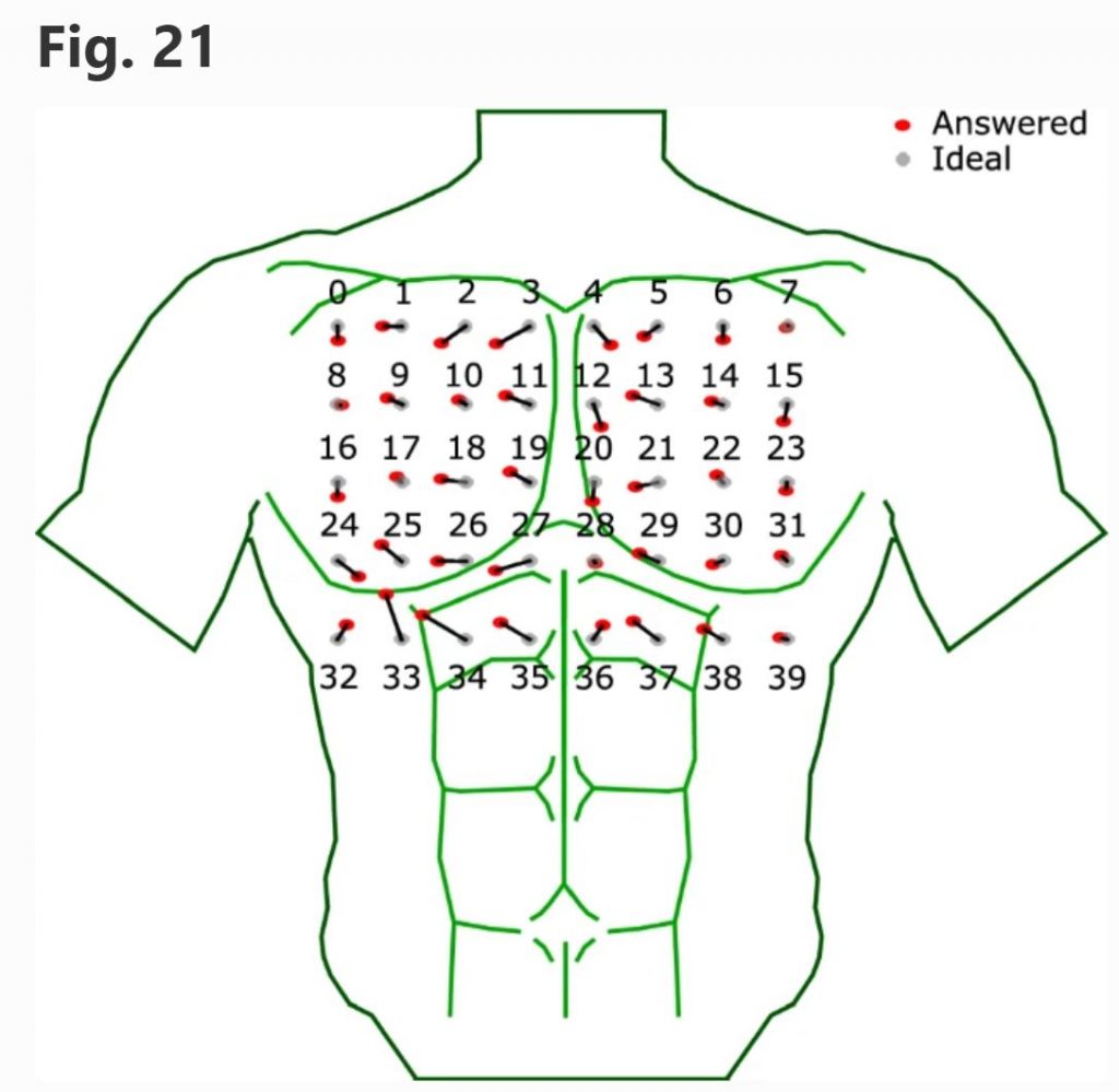
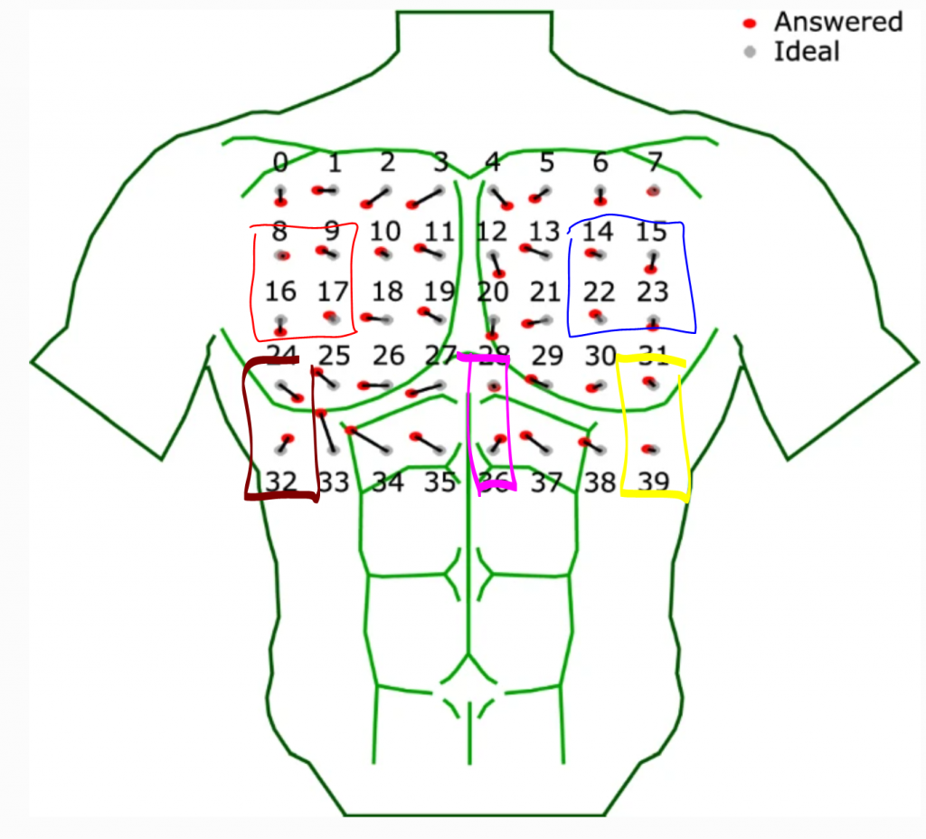
In conjunction with testing the Arduino wifi rev 2, I also finalized my research on the haptic feedback locations on the torso. This was based on research from Pneumatic and acoustic suit: multimodal haptic suit for enhanced virtual reality simulationby Daeseok Kang, Chang-Gyu Lee, and Ohung Kwon published in Virtual Reality in 2023 and Whole-body mapping of spatial acuity for pain and touch by Mancini et al. published in Annals of Neurology in 2014. From Kang’s paper, I took this mapping of motors shown below and noted where there was the smallest gap between the red and the grey dots for the same corresponding number. These are the most ideal spots to place a haptic feedback point since it’s where users most accurately detected the location of the motors used in this study. In figure 3, I isolate the most ideal spots to place a haptic feedback by placing them into individual blocks. The blocks signify that it is a single feedback point, i.e. motors in this spot are synchronized to work effectively as “one” motor
Figure 2
Figure 3
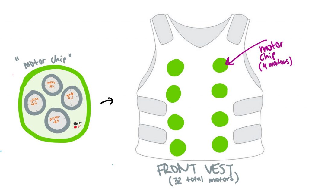
Based on Mancini’s paper, I got a good sense of where to place the motors on the shoulders of a person’s body, and together I placed the feedback points on a 3D model of a body as shown in figure 4. Together, there are 8 motor blocks on the back, 2 on each side, and 6 on the back. All the motor blocks have 2 motors inside, with the exception of the 2 motor blocks on the front torso, which have 4. One of these blocks will placed over the heart, which we could use to localize the low health algorithm (to stimulate an increased adrenaline rush different from all other points on the torso).
Figure 4
Lastly, I worked on configuring the wireless Xbox controller we ordered for the game, and it worked seamlessly. I tested this out on a gamer who stated they didn’t have any problems while playing with the controller. Additionally, I had the gamer play at a distance well over 6ft and the connection was still maintained. This is 1 step towards our wireless experience. I don’t anticipate having to test the controller again until we have finished the motor/light integration on the vest itself.
Progress On Schedule
In terms of the schedule, I am very worried about the getting the connection set up on the Arduino wifi. I think I will have to do more testing + reach out to the TA in order to resolve this. If it can’t be resolved, we can always order the ESP32 board detailed in last week’s report. Other than that, I’m worried about getting the PCB design. I have no prior experience with PCB designing so I will have to do some Eagle tutorials while working on the previous tasks mentioned.
Deliverables for next week
For next week, I hope to have the Wifi connection with the arduino established so we can start testing the range and bandwidth. I also need to order RGB lights, for this I’m planning on ordering 8×32 RGB led matrix off Amazon, but need to check the specs (i.e. Arduino compatibility, voltage required to power, #of input pins required) before I commit to ordering. I also need to do some Eagle tutorials if we’re going to order a PCB before spring break. Lastly, I will work with my team to submit a project report before spring break.
This week I tested the vibration of the coin motor using an Arduino in order to get a sense of how strong it felt to the human touch. At first, I programmed it using a digital pin which can only be programmed to either high (highest vibration strength) or low (off). I found this created an extremely unpleasant sensation, the motor did not need to be at maximum strength. Instead, I programmed it using an Analog pin (known as a PWM pin on an Arduino) and set it to half strength which sits at about 127 on a scale of 0-255. The simple code I wrote for this test can be found in our Github, under the “arduino-testing” repository
Next I researched how to get more PWM pins on an Arduino. An Arduino only carries 6 PWM pins, and for our implementation, we’re going to need around 20 pins. This meant I need to either convert the digital pins to PWM pins or look for a hardware alternative. I went with the former solution seeing as we already have several Arduinos on hand to test and waiting for another piece of hardware was not going to effective. This brought me to use the softPWM library available on the Arduino IDE, which is capable of converting digital pins to PWM pins.
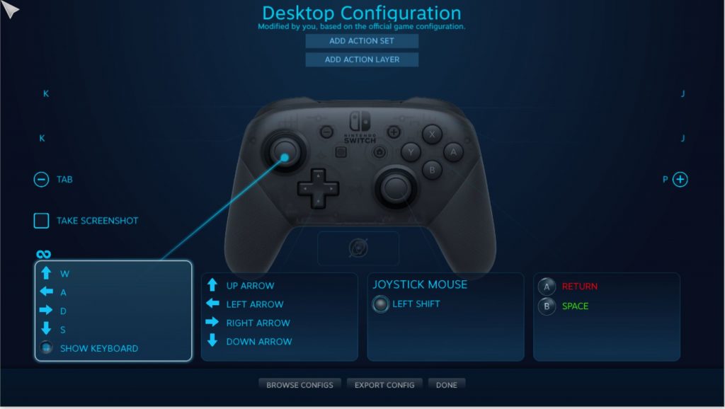
I also researched the possible avenue of a joystick with an accelerometer as an input device in order to remove the keyboard from the gaming experience. As mentioned in the team status report, we had to abandon this idea based on our user survey. Users stated this type of control is very unpopular, and going out of style in the gaming community. Thus, our team is advancing with the wireless Xbox controller idea and I used my time this week to reconfigure the keys of an existing Nintendo controller I had, to keyboard keys. I reconfigured the keys through a gaming platform called steam as shown in figure below. I had to be thoughtful about where exactly to map the keys, this required me to think about where a person’s thumb naturally lies when holding a controller (this should correspond to a <space> hit on the keyboard), what keys are they most likely to hit during the game (jump and attack) and where I could map those on the controller. I used my own Nintendo controller for this test, but since it only has a wire capability, we are going to order an Xbox controller for the final project design and the logic still stays the same.
figure 1
I also needed to ensure that the suit remains wireless. To do so, the Arduino inside the vest which connects all the motors and RGB lights together, needs to be wireless as well. Since we don’t have any input sensors in our suit, it only needs to act as a receiver and our laptop which holds actual parsed user game data, will act as a transmitter. I landed on two possible solutions to achieve this: (1) using a regular Arduino but attaching a Wi-Fi shield. This required us to buy a $69 XBee antenna and it doesn’t have SDA/SCL pins we would need in order to expand our pin range and use I2C. (2) using an Arduino Wi-Fi Rev 2. This solution requires us to buy an expensive Arduino ($53) but it works perfectly as long as we connect the Arduino to the same Wi-Fi as the Wi-Fi on the transmitting laptop. (3) Using an ESP 32 board. It’s fairly priced ($13.99 for two boards) but I didn’t explore this solution too much. It was brought forward by our team’s TA after we ordered the Wi-Fi Rev 2 but if the Rev doesn’t work, we will definitely have this to work with.
Progress on Schedule
So far, I’m on schedule so that we can begin simple integration tests over the course of next week, but I will need at least some time to myself in order to test the wifi rev 2 before we can do effective integration testing.
Deliverables for next week
I’m currently still researching what points on the torso will feel . I landed on a research article that gave a good point for the shoulders, but I need more for the front and side torso. I think over the course of the next week, I will finalize these feedback points by reading more research articles and map them in order to move forward. I will also look more into how we want to package the motors for each feedback point, exploring a PCB board as an option since it is easy to reproduce and scale.
ECE Courses
I think the most useful ECE courses that cover our design principles would be 18300 (getting the motors and sensations correctly) and 18213 (general coding abilities). Relating to Arduino and sensor knowledge, 60225 (intro to physical computing) helped immensely since we were working on bringing projects with input devices to life using Arduino.
This week, I worked on researching the best motors to provide a haptic feedback. I landed on two types of motors: pager motors and mini vibration motors. Each of the motors comes with drawbacks and advantages, with the advantage of the mini vibration motor being it’s small and has compact shape that will minimize the weight of the vest. The pager motor will be more difficult to mount to the vest because of its boxy shape, so I believe we are going to go with the mini vibration motors.
I also spent some time prototyping the design of how the motors will function inside the vest. Since the mini-vibration motors are smaller than the size of a quarter (10mm diameter), my initial thought is to arrange 4 motors into a “flower” that will function as a single feedback point. To mount this, I will laser cut a chip made out of acrylic that can support the 4 motors in a pattern (as shown in Figure 1). In order to actually get the chip into the vest, I thought of a method to get a thin, expandable material (i.e. spandex) which we could sew into the inside lining of the vest itself. We would create a “pocket” of sorts with this material in which we could take the motor chip in and out of + connect to common ground/power + connect to the STM which would rest in the back of the vest.
figure 1
Lastly, I did some research into the best RGB lights for the haptic suit, and landed on the neopixel ring light. This was best suited for our project since it will outline where there is haptic feedback point is on the vest, and is easily adaptable to an Arduino (there is a corresponding neopixel library that we can download).
Progress on Schedule:
We’re still on schedule, but need to work diligently this next week since we spent a lot of time researching. I think the biggest roadblock right now might be getting the parts in order to test them. I have a mini vibration motor in my own personal Arduino kit, so I can test and approximate if 1 motor per haptic point is enough, or we really do need 4. Once we get more motors, this will be easier to determine.
Deliverables for next week:
Over the next week, I hope to test the motor pattern and determine if it simulates a feedback that corresponds to the game and doesn’t deter from the experience. I will also determine if its too many/not enough motors or if the motor needs to be changed for a specific point (i.e. maybe the motor over the heart needs to be stronger than the rest to simulate a thumping sensation). If the motor chip design works well, I will then work on creating a “motor chip flower” class in the Arduino IDE in order to modularize the system since we will be working with a lot of motors, and they all need to be synchronized. When an instance of this motor class is called, it will activate the motor flower chip as one, so that it seems like you are controlling only one motor while hiding the fact that it is actually 4.