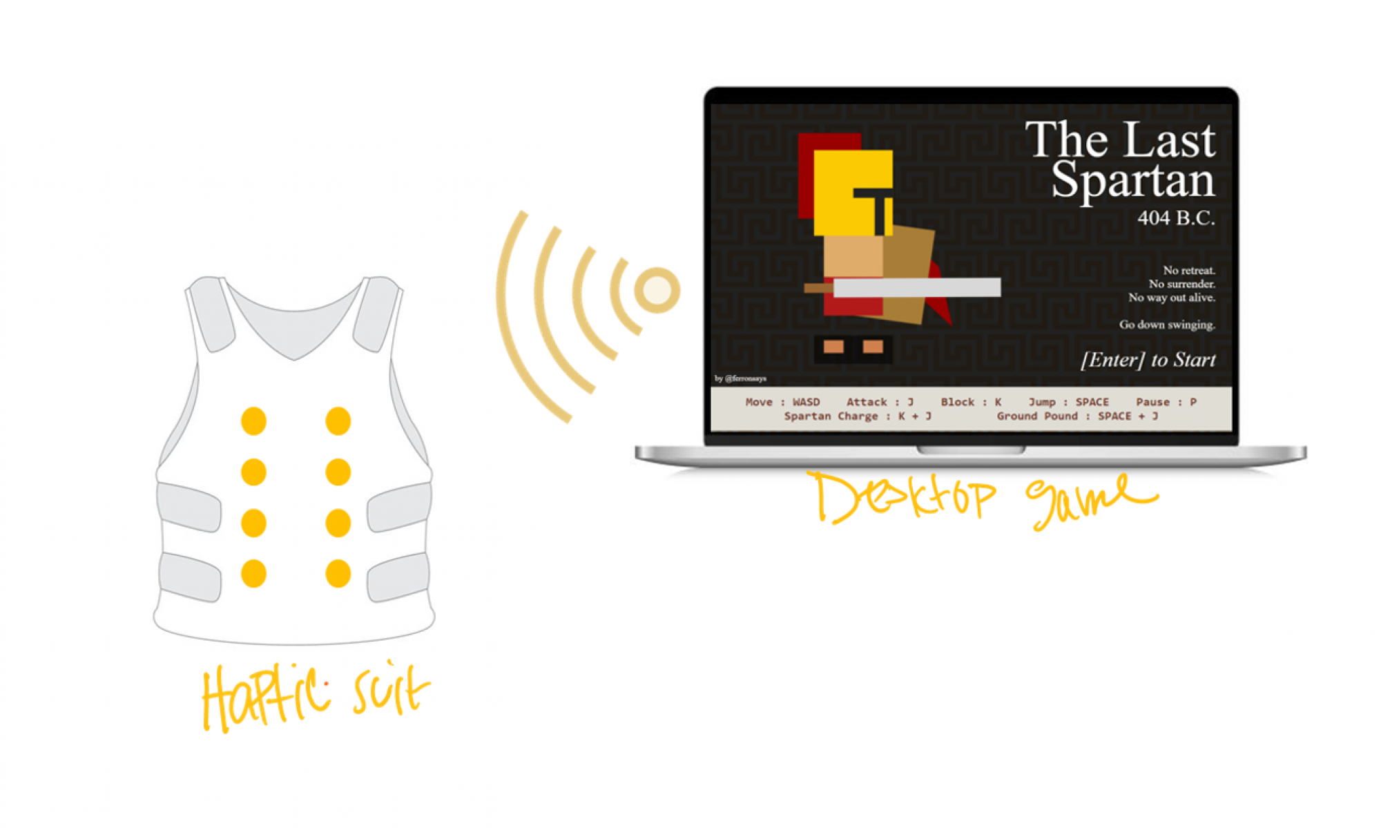
Updates for the week
This week, I focused on parsing the POST request data from POSTMAN. I got this to work successfully, but after consulting with my teammates Bethel and Sophia about what the incoming data is going to look like, I realized that parsing data from POSTMAN is not the same as parsing data from JSON, but we agreed that any incoming data will have the string format “? MA, LA”
Where MA is a string that holds any of the 5 string values: ” “, “FJ”, “HS”, “HL”, “LH” corresponding to a motor action (i.e. FJ->Forceful Jump, HS->Hit Small, HL->Hit Large, LH->Low Health). LA holds similar 5 values: ” “, “W”, ” HS”, “HL”, “W” which corresponds to a light show action (i.e. W-> character in water).
I will parse this string format and hold the corresponding values in a struct so that the motor and light algorithms are able to case on these value instantly and send the correct response to the motors/lights.
These will start with a ‘?’ to let the IDE know we’re receiving the proper data.
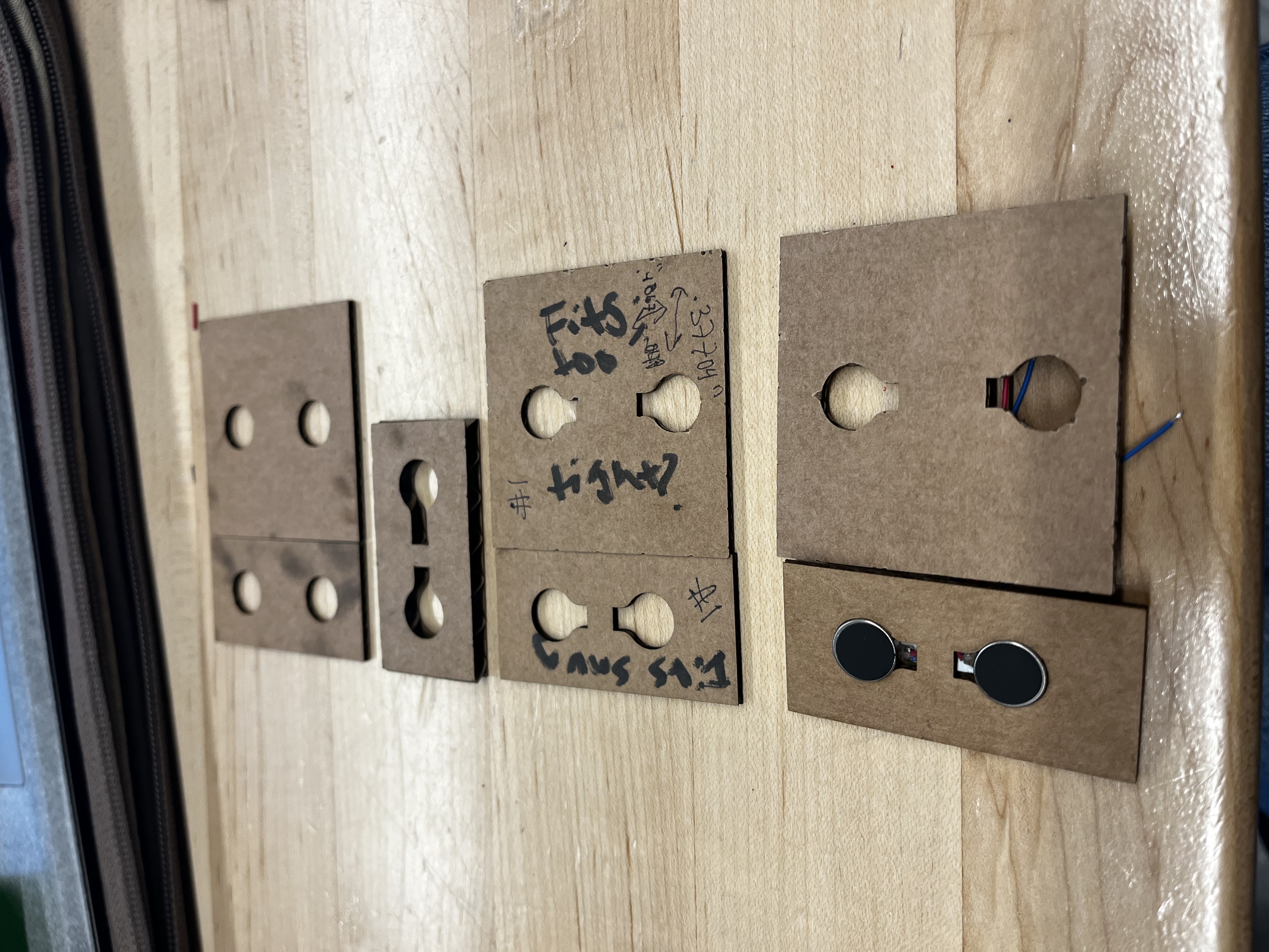
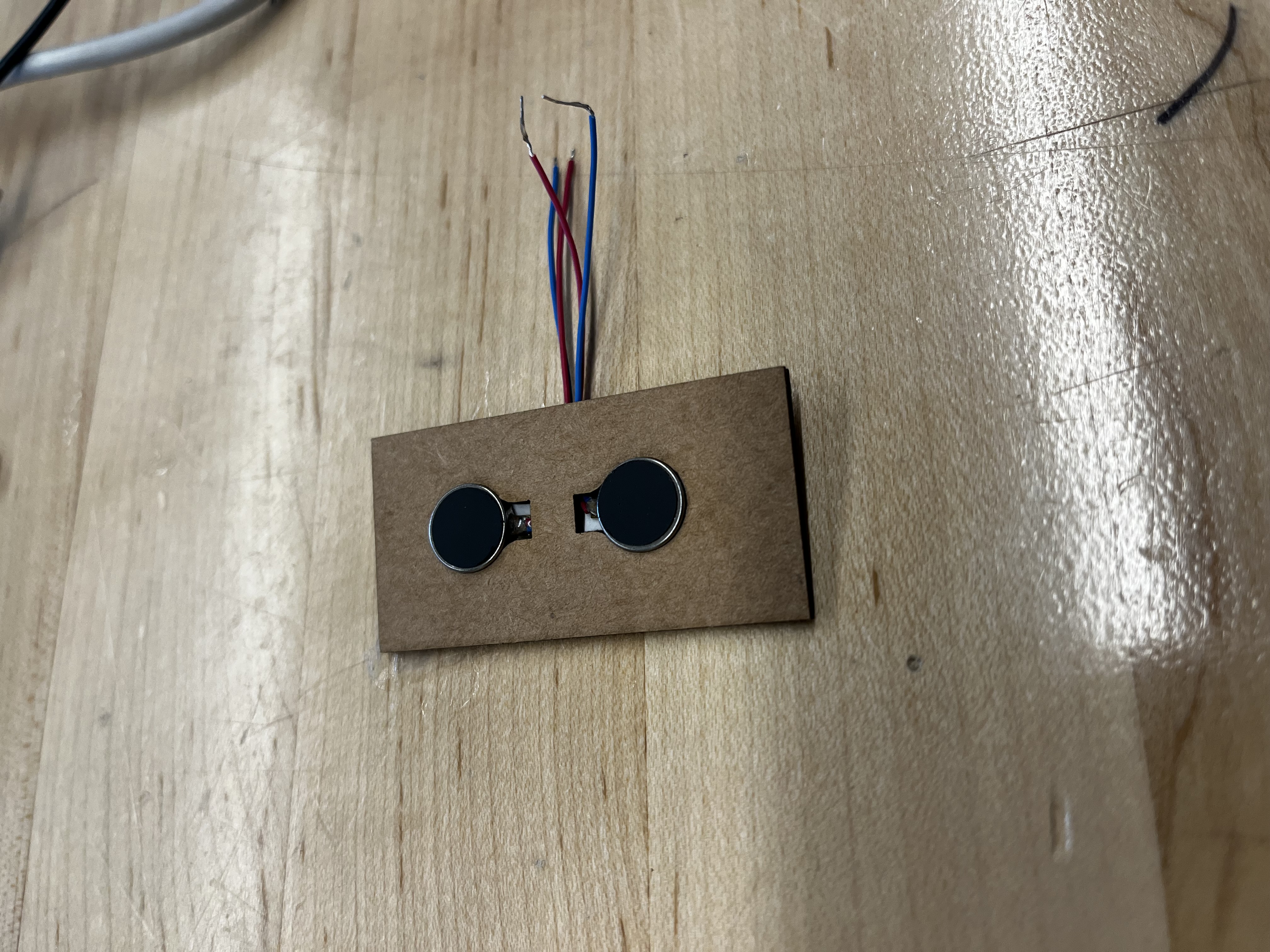
Next, I worked on prototyping the actuator mounting board. I started by creating a CAD model with squares and added 2 mounting holes 10mm in diameter to these squares. I laser cut them on (1/32)” cardboard then realized the motor surfaces weren’t flush with the cardboard because they didn’t have a notch for the wires in sticking out of the motors. I then added a notch on CAD and did several iterations of prototyping on cardboard. I laser cut on slightly thicker cardboard but the motor just fell out because the gap couldn’t support the motor, then went back to prototyping on (1/32)” thick cardboard. The image below shows the iterating process. I finally landed on a design which has holes 9.7mm in diameter (slightly smaller to ensure the motor doesn’t fall out) and a gap of 5mm between the two motors. I also tested these at half/full power and it wasn’t unpleasant at 5 mm apart, and did not fall out of the mounting hole.
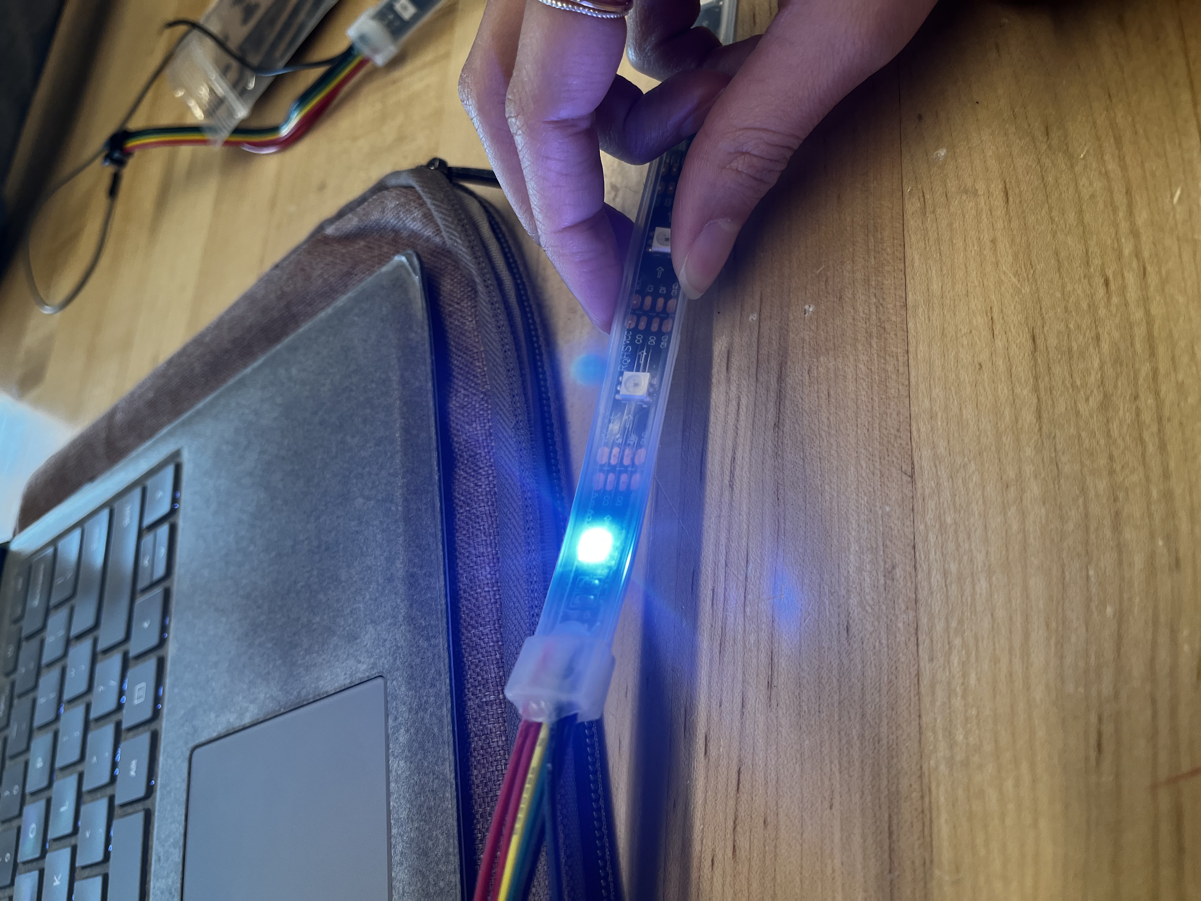
I also worked on setting up the RGB lights. I turned on 1 LED but need to spend more time on it in order to have the Low Health light show functional as I stated in last week’s status report.
Progress On Schedule
Since I am no longer designing the PCB board, I only have to focus on getting the lights working, the motor mounting plate finalized, and Arduino working wirelessly. I have the Arduino working wirelessly already, it’s just a matter of parsing data from JSON, not from POSTMAN. I’m behind on getting the light algorithm working, so I will spend tomorrow (3/19) working on it.
Deliverables for next week
For the final motor placements, I’m intending on using a different, more durable material. I’m hoping to finalize choosing which material this is going to be, I’m in-between acrylic or a silicone sheet because of its lightweight and heat resistance. I plan on talking with the professor more about the pros/cons of each material.
Once Sophia has the finished dimension for the PCB, I plan on editing the CAD model to make space for the PCB on the actuator mounting board and laser cutting 8 of these to have them ready for the interim demo. The idea is that these 8 will go on the front of the vest, and I will make a plan to mount + wire them on the vest so that they do not move.
I will also get the low health light show algorithm working by the end of the week, so that we are in good standing to have at least one action completely done before the interim demo.