Team Status Report for 4/29/2023

What are the most significant risks that could jeopardize the success of the project? How are these risks being managed? What contingency plans are ready?  

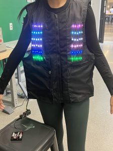
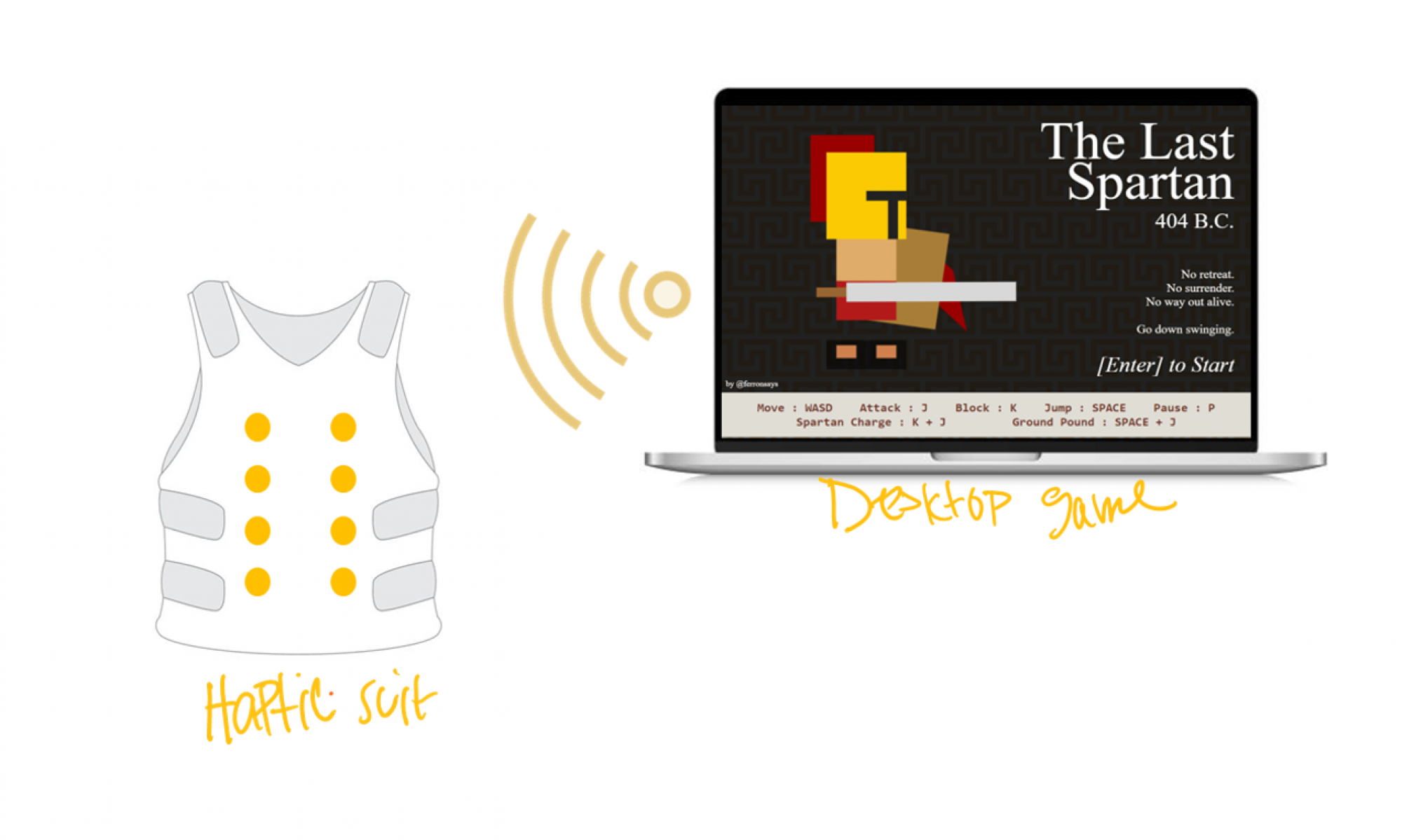
This week we have successfully managed to incorporate the rest of our motors into the back of the vest. On the contrary, we still need to make both the integration of our hardware and software components more reliable. This involves us having to parallelize our motor and light code which we plan to accomplish this weekend. Moreover, we aspire to establish wireless interfacing between The Last Spartan game and the vest (post MVP).

Another risk we are preparing a contingency plan for are wiring issues. We tried to mitigate this risk by using ribbon cable to improve clarity of cabling, making debugging far easier.

While improving upon our hardware and software integration we will simultaneously be working on our poster and project video this week. The risk here lies in our time management. We plan to delegate different tasks amongst ourselves to help maximize our productivity and minimize any risk associated with running out of time. 


Were any changes made to the existing design of the system (requirements, block diagram, system spec, etc)? Why was this change necessary, what costs does the change incur, and how will these costs be mitigated going forward?  

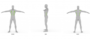
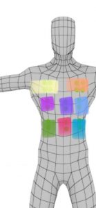
The block diagram was changed last week to include the PCBs. Some minor motor system numbers were changed to fit with the actual wiring of the vest. 

We also pivoted from using the Puppeteer library to track the remaining three in-game actions of low health, getting hit by a small enemy and getting hit by a large enemy within the past week. The problem with this library lies in the fact that it didn’t allow us to customize the game as per our user and design requirements. It has since been eliminated from our existing design of our system.


List all unit tests and overall system test carried out for experimentation of the system. List any findings and design changes made from your analysis of test results and other data obtained from the experimentation.

Hardware

  • Recheck that each motor system works individually
  • Motor responses are correct
  • Verify that moving vest doesn’t disturb motor systems
  • Verify that the light systems have correct response
  • Check that implemented code for last two motor systems goes off with other motor code

Software

  • Test that the Node JS server prints out the data we want it to relay
  • Verify that the Node JS server can relay data from a generic website
  • Check whether the Node JS server can send correct data to control a single motor circuit 
  • Validate that the Node JS server can send the information generated by one in-game action, namely forceful jump
  • Validate that the Node JS server can send the information generated by all the in-game actions, namely forceful jump,  low health, getting hit by a small enemy and getting hit by a large enemy
  • Test that the latency of our system lies under 100 ms
  • Verify that our precedence algorithm correctly dictates the outputs we want to see in the chronology of the importance of events

Implementation

  • Verify that motors systems and lights go off at the same time
  • Try the software 10x times to determine reliability
  • Try the software on 2+ laptops to determine reliability
  • Have 10 people play the game to gain more user data, feedback, and check the vest is operating correctly


Provide an updated schedule if changes have occurred. 

We have attached our updated schedule in this link. We are working to parallelize our motors and lights as well as achieve wireless interfacing between the game and vest (post MVP).


This is also the place to put some photos of your progress or to brag about a component you got working.

Link to image of the PCBs at the back of the suit

Team Status Report for 4/22/2023

What are the most significant risks that could jeopardize the success of the project? How are these risks being managed? What contingency plans are ready?  

We need to make the integration more reliable. 

One of the risks we could encounter is a problem we didn’t foresee. We hope to mitigate this by doing more user testing so other people can help uncover unknown problems. We completed about 1 hour of user testing today. As a contingency plan for if any hardware breaks, we have about ½ of our hardware resources as backups in case something breaks or something goes wrong. 

Another risk we are preparing a contingency plan for are wiring issues. We tried to mitigate this risk by using ribbon cable to improve clarity of cabling, making debugging far easier. 

Were any changes made to the existing design of the system (requirements, block diagram, system spec, etc)? Why was this change necessary, what costs does the change incur, and how will these costs be mitigated going forward?  

We finally changed the block diagram to include the PCBs. Some minor motor system numbers were changed to fit with the actual wiring of the vest. 

We pivoted from using the Puppeteer library to track the remaining three in-game actions of low health, getting hit by a small enemy and getting hit by a large enemy. The problem with this library lies in the fact that it didn’t allow us to customize the game as per our user and design requirements. An instance of this was our lack of ability to incorporate the motor intensity bar into the user interface as was expressed through our Ethics feedback session.  

Provide an updated schedule if changes have occurred. 

Schedule

This is also the place to put some photos of your progress or to brag about a component you got working.


Team Status Report for 4/8/2023

What are the most significant risks that could jeopardize the success of the project? How are these risks being managed? What contingency plans are ready?  

Since the PCB arrived this week and works as intended, the next significant risk would be not getting the proper data sent between the Node JS server and the WIFI Rev. This step is integral towards having a completely wireless experience when using our solution. As of now, the Node JS code is able to send data to the WIFI Rev, it’s just not the game data we want. We do want to move forward in order to get to the testing and validation stage of our project, so if we can’t get it to work by the end of the week, we will revert back to having a wired arduino to the laptop. The arduino is able to respond to Node JS data when it is connected to a specific port, as Bethel demonstrated in earlier status reports so we should have no problem if we switch to this.


Were any changes made to the existing design of the system (requirements, block diagram, system spec, etc)? Why was this change necessary, what costs does the change incur, and how will these costs be mitigated going forward?  

Since we had an interim demo this week, we ordered ribbon cables and the remaining PCB parts. The PCBs were a component we added on later within our design process. Our current design of our motor systems benefit from having an efficient distribution of power to our motors, which makes for both a bettered immersive experience and more distinguishable motor propagations for the user


Additionally, we decided to laser cut our “pocket” squares in order to achieve a more uniform look and stay consistent with sizing. This saved us a considerable amount of time as well, since we no longer have to sit and manually cut 10+ squares. We used fabric that was free and available to us through IDEATE. 


Provide an updated schedule if changes have occurred. 

We don’t have an updated schedule, but plan to start validation testing by 4/14. Given that the rest of the PCBs will not arrive by then, validation will take us up till the final demo.

Team Status Report for 4/1/2023

What are the most significant risks that could jeopardize the success of the project? How are these risks being managed? What contingency plans are ready?  

Keeping an organized wiring system is one of the most significant risks going forward. For our demo, we have 22 gauge wires from the Arduino to each motor. This takes up a lot of space and for the 6 motor systems we have, the cable management is getting pretty messy. We currently have 5 colored wires for the 6 systems, but when we reach 18 motor systems we’re going to need a better system. For the demo, we’ve made a wiring diagram to reference that can be found here. Moving forward, to manage these risks for the final, we plan on using ribbon cables and crimp pin connections. With ribbon cables, we can have one bus of cables which are flat and organized. When the cable reaches a motor system, it will branch out to connect to the system. 

Were any changes made to the existing design of the system (requirements, block diagram, system spec, etc)? Why was this change necessary, what costs does the change incur, and how will these costs be mitigated going forward?  

The orientation of the motors within their casing needs to be turned 90 degrees to the left (clockwise) in order to minimize the risk of breakage.

For the interim demo, we are changing how we implement the motor holders, power system for the lights, and motor system driving device. For the motor holdings, we are using cardboard instead of the rubber we plan to use for the final. This is to save money in our prototype system. We are using a 6V battery supply made up of 4 AA batteries instead of the 9V battery with a buck converter we plan to use in the final. This is because we are currently waiting for the buck converter to come in. Lastly, we are using the Arduino to power the motor systems instead of the servo driver device. This is for several reasons. The servo driver device does not provide enough power to drive the motor systems until we receive our PCB boards. We want to deliver a product that can provide the sensations we want for the final project so we are instead wiring the motor systems directly to the Arduino board. The board is limited to 6 PWM outputs so this solution will not work for the final. 

Provide an updated schedule if changes have occurred. 

Individual tasks of each member will be updated to be taking place simultaneously with our integration of the software and hardware components. 

With regards to the software side of things, we are still looking to track the low health, small hit and large hit game events. Moreover, we look to incorporate our PCB to our original design the moment it arrives. 

This is also the place to put some photos of your progress or to brag about a component you got working.


Cascading lights


Progress with wiring up our motor systems

Team Status Report for 3/25/2023

What are the most significant risks that could jeopardize the success of the project? How are these risks being managed? What contingency plans are ready?  

We were very careful and sought a lot of feedback from our TA and professor when designing our PCB for the motor systems. However, there could still be an unforeseen problem when we start to test them next week. Without the PCB, our vibrational feedback will not be as effective and may jeopardize the sensations we want our users to feel. 

We also noticed that the RGB lights draw a significant amount of current, so much so that the 6V battery supply to the microcontroller was not enough to keep all the lights running at a high brightness setting. If we add a second power supply, the lights are able to run at a high brightness and there is some heat emission. The heat emission is not noticeable or uncomfortable when you put on the vest, only if you place your hand directly over the lights. We don’t anticipate the heat of the lights being a risk factor, but we did want to acknowledge it. 

Were any changes made to the existing design of the system (requirements, block diagram, system spec, etc)? Why was this change necessary, what costs does the change incur, and how will these costs be mitigated going forward?  

This week, we had our ethics discussion. The other groups brought up several points we did not originally consider in our design. One of the biggest concerns brought forward was the idea that someone could remotely control the vest using the wireless controller. When we decided to move to a fully remote system, we had not considered how incorporating a remote controller might be dangerous to the person inside the vest. To avoid this, we plan on implementing an emergency stop switch into the vest which can turn everything off immediately. This will allow people who feel uncomfortable to stop the vest. This emergency stop will be a physical system between the power and the devices that are running, preventing any delays sending a signal to the Arduino may cause. 

Other concerns included how hot the vest would get and how accessible our product would be for people who have limited arm mobility. For the heat, we were able to test it out, as stated in our risk factors. We interpreted the latter as a concern of putting on the physical vest. To make putting on the vest a smoother experience, we decided to put optional Velcro strips that run horizontally across the middle of the vest (under the zipper) so that a user is able to secure these strips instead of the zipper, which may be hard to use.  

A design change we made this week was the inclusion of Velcro strips to the inside lining of the vest in order to vertically secure the light and motors systems. The user will not see these strips, but it does allow us as the designers to easily access the motors/lights, provides minimal movement, and a seamless outside look that avoids any additional sewing. 

Provide an updated schedule if changes have occurred. 

We are on schedule. Next week, we will focus on integration and cleaning up our individual contributions. 

What we got working. Video of putting on the vest can be found here

Figure 1: Vest light integration
Figure 2: Vest on mannequin
Figure 3: Clean wiring through suit

Team Status Report for 3/18/2023

Most Significant Risks

The PCB needs to be designed and simulated before sending the design out for printing. If we don’t get the design sent out soon, this might delay our current plan to have a basic full-system operation working before the interim demo. We are going to manage the risk of not getting it done in time by finishing the design by Monday of next week. This will allow us about one week of printing time and one week to test the full hardware with the PCB. Our interim demo is in 2 weeks, so we hope to have a full system demo for at least one in-game action working by then. Our contingency plan is to have the interim demo with only one motor in each subsystem directly connected to the motor driver. This will allow the users some idea of how the feedback system will work even if it won’t provide the amount of feedback we plan to have for the final. 

Changes to Existing Design

Upon consulting with Omkar and Professor Gary Fedder, we have decided to completely abandon the game code translation process. Instead we will be going back to the original strategy of using JavaScript event listeners to track different game actions. This changes our software design in that we will be using socket.io to relay information to the Node JS server and the server will then use the serial port package to send this information to our Arduino. This change was necessary because limited progress was made in transferring the AI component of the game code from Javascript, HTML and CSS to Node JS.

Additionally, we previously had differing ideas on how the PCB would be mounted and connect to the motors, but upon our meeting with Professor Gary and Omkar this week, we decided that the motors should be mounted separately, and the PCB should be attached to the motor mounting plate instead of it being one entire system. This will make our design more modular to changes since it’s easier to laser cut a new mounting plate than it is to design a new PCB if we want to make slight changes to the motor positions. 

Updated Schedule

N/A. Somehow, we’re not off schedule yet. 

Team Status Report for 3/11/2023

Current Project Risks

As of now, the most significant risk we face as a team is managing the amount of connections and wires necessary to mount our motors and lights to the haptic vest. We need to ensure that our wiring will not become disconnected or tangled as a player moves with the suit, takes it on and off, and adjusts the straps on the suit. If a wire becomes disconnected, it may result in a motor/RGB light system or the suit all together failing to turn on, thus adversely impacting the player’s immersive experience. Although we are not at the stage of mounting the motors/lights, we need to keep this in mind in order to save us the trouble in the future. As such, we are designing our circuit schematic to use color-coordinated ribbon wires that correspond with specific systems in order to locate systems with ease. Moreover, we plan to measure the wirelength from each connection to the Arduino in advance, making sure it is long enough to expand and contract with the different sizes. 

Changes to the Existing Design

As Amelia stated in her report last week, we have decided to add motor systems instead of individual motors to each part of the torso. We’ve determined this is necessary because, while one motor has a large feedback while someone isn’t playing a game, adding the game component may distract a person, lowering the impact they feel from one motor. To mitigate this, we can increase the amount of force a person can feel. 

We have also decided to add a slide bar on our website page so people can customize the power of the motors. With the upgraded motor systems, the motors will achieve much more force. However, we have had questions about how to make our project more accessible to people who may feel sensations differently. We think that adding this customizable power option will allow users to choose what they feel and have a more customized experience.

Schedule Changes

There has been no update to our schedule since last week. 

Components We’ve Improved Upon

We submitted our design report which established a lot of the nuances of our design implementations such as: game action precedence, configuration of motors, and motor haptic algorithm sequence. 

New Tools to Learn

Since we added motor systems instead of singular motors in each area of the chest, we’ve decided to mount these motors to a PCB.  The PCB will take the PWM signal from the servo driver and expand it to drive multiple motors with minimal power and current loss.

Since our team has no prior experience designing a PCB, we will have to allocate time to go over Eagle/Fusion 360 tutorials since these platforms are dedicated to PCB layout design.

Team’s Status Report for 2/25/2023

What are the most significant risks that could jeopardize the success of the project? How are these risks being managed? What contingency plans are ready?  

The most significant risks that could jeopardize the success of the project are getting the vibrations motors operational. This means we need to come up with a way for the current output from the servo driver to increase. The risks being managed are reassigning tasks to research either a solution to increase current from the PWM pin, or to create a custom PCB to accomplish the task. 

Were any changes made to the existing design of the system (requirements, block diagram, system spec, etc)? Why was this change necessary, what costs does the change incur, and how will these costs be mitigated going forward?  

Additions made to the existing system are adding an extra block between each servo driver output and a vibration motor. This was necessary to ensure the motors will have enough haptic feedback for the gamers to feel. This will increase the cost of the system. A fully custom PCB that connects to the Arduino I2C and outputs PWM on two pins would have been better, however with little experience with creating custom PCB, figuring out custom I2C communication protocols on the PCB may be a bit too much for a first project. 

Provide an updated schedule if changes have occurred. 

If the PCB is designed and sent out before Spring break, it can be tested when we get back.

This is also the place to put some photos of your progress or to brag about  component you got working.

We’ve finalized where on the body the motors should go. We also got our vest in and, despite it coming in a small size when we wanted a larger size, it will work perfectly for the haptic suit. We found that turning it inside out will allow the RGB lights to shine through the material.


Enumerate how you have adjusted your team work assignments to fill in gaps related to either new design challenges or team shortfalls (e.g. a team member missing a deadline).

We have adjusted the team work assignments by compressing some of our larger milestone projects (like programming a motor algorithm) to make space for getting a necessary custom PCB built. 

Team Status Report 2/18

Current Project Risks

Currently, the most significant risks that could jeopardize the success of the project revolves around our individual tasks. While we may find challenges within our individual tasks, those will be covered by our personal status reports. The main risks are: Sophia figuring out how to drive 2-wire vibration motors with the 3-wire PWM pins, Bethel tracking the actions and coordinates of the enemies within The Last Spartan game, and Amelia with pinpointing where to package the vibration motors in the vest that corresponds with existing spatial acuity data. To manage these risks, each member will focus on fitting their part. Sophia will stagger between testing the motors and determining if a PCB board could be configured to convert the necessary power. Amelia will continue reading existing research on vibrotactile stimuli on the torso as well as making sure the Arduino Wifi Uno is able to receive information seamlessly without noise interruption. Bethel will identify the event handlers dedicated towards different types of enemies within the game.  

We also foresee integration as a possible risk. To mitigate this, we plan to do basic integration tests next week. These tests will include sending data from NodeJS server to Arduino and packaging a single coin motor in the vest to ensure it does not move beyond our constraint of 1” radially once on.

Changes to Existing Design

We’ve been thinking about how we could make the experience of a haptic suit more seamless, namely with a keyboard-free experience. Our first idea was to build a joystick input device with an accelerometer that a user could use to swing vertically up and down in order to “attack” enemies in the game. After surveying various gamers and doing our due-diligence with our own research, we found that this type of input is called a “waggle controller”. The waggle controller was popularized by Ninetendo in the early 2000s, being a common feature in games such as Wii Sports, Super Mario Galaxy, Donkey Kong Country Returns, The Legend of Zelda: Twilight Princess, and Rayman: Raving Rabbids. It’s highly unpopular amongst gamers because of the general “lack of skill” it requires out of the user, only random movements to get it to work. Instead, we will be using a wireless xbox controller that a user can use to control their in-game actions. This is the most popular and well-known type of controller because of its ease of use and affordability, running around $50 for a wireless option. We will be mapping the keys on the controller to the keys on the keyboard using the platform “Steam”. We will also be changing the in-game instruction graphics to reflect the controller being the input device instead of the keyboard. 

We also spent a lot of time thinking about our design implementation block diagram. This helped us understand the interdependencies of our tasks. This will allow us to move forward with our parallel tasks knowing what has to be done to integrate the system.

As we’ve proven, moving forward, the best way to vet our design and implementation changes is to survey our users. Ask them what they want in order to improve their experience. Being that we are not gamers ourselves, we aren’t reflective of a typical user and thus can’t speak to what they would like. We can only implement changes and bring the system to life. 

Principles of Engineering Utilized in Project

We utilized multiple principles of engineering, science and mathematics to develop our design solution including I2C protocol, server design, researching spatial acuity in the body, event handling in JavaScript and Circuit design using an Arduino.  

We are employing the engineering design process in every aspect of our project. We have focused on ensuring our project is very modular with lots of parallel tasks which can be completed by our group simultaneously. We are currently working on the research and prototyping phases of the engineering design process.


Team Status Report for 2/11/2023

The most significant risk that could jeopardize the success of the project is not receiving our parts in time, which would push our planned schedule back. We also have to consider researching the best motors for our chosen haptic feedback points before ordering (this is going directly out of our budget so we don’t want to spend excessively on motors we won’t end up using). However, we have to consider that ordering one type of motor at a time would delay our project if it turns out that the chosen motor type does not meet our requirements. To mitigate this risk, we have our own personal motors/Arduinos that we will be using for testing while we wait for our parts.

On Sunday, we had an additional meeting with Mimi Sung, the president of CMU Esports (student-run gaming organization). She brought up a valid point that even if we provide excellent haptic feedback, the fact that the gamer is still confined to a keyboard may diminish the full feedback experience. This inspired us to consider adding a physical input device so that the user can control their in-game actions without the use of a keyboard. 

This physical input device we first thought to build is a wireless joystick modeled after the nunchuck controller joystick (as shown in Figure 1 and 2). The joystick in the player’s left hand will control the movement of the player, while the joystick in the player’s right hand will include buttons (as shown in Figure 3) that can control the player’s actions (i.e. forceful jump, attacking an enemy, diminishing health and getting hit).

Figure 1
Figure 2
Figure 3


Another avenue we could take to achieve a keyboard-free experience could be taking a regular wireless Xbox controller and configuring it to the monitor the game is being played in (as shown in Figure 4). We would have to find a way to configure the X-Y-A-B keys on the controller to W-A-S-D keys on the keyboard, and get that information to the game itself. It’s a possible avenue, but definitely needs more research before we decide to go with it or build our own nunchuck controller.

Figure 4

In consideration of our meeting with Mimi, we changed our project proposal and gantt chart to reflect creating the keyboard-free experience. We allotted time to research, develop, and test this system. 

Our project includes considerations for the welfare, safety and economic capability of our intended user. A driving force of our project is to make our haptic suit cheaper than the industry standard which runs around $500-$3000, our solution will run for less than $200. We also aim to design our system around all sizes, in order to promote body inclusivity and comfortability from wearing our vest.