Project Video
Final Poster – PowerPoint and PDF
PDF: Demo Poster
PPTX: Demo Poster
Matthew Shen’s Status Report for 4/30
This week, we worked mainly on optimizing the software. I mainly worked on trying to better align the LEDs on the hardware side as there were some instances of misalignment randomly appearing. Next week, I plan to take an oscilloscope to each LED to ensure they each exceed the VIL of the muxes. I will also be working to finish our poster and demo video this week.
We are on schedule as we have completed MVP and are working towards our reach goals now.
Final Presentation Slides
Video – Touch TrackIR Preliminary Testing
Darwin Torres’ Status Report for 4/23
This week, I helped the team in performing the initial tests of completed integration of all subsystems. Initially, there wasn’t much I could do related to my subsystem as I had to wait the frame to be completed and tested. In the meantime, I worked on the final presentation and report. Once the frame was completed and Matt S and Matt K were able to confirm successful integration of their subsystems, I jumped in to test the integration of my subsystem. As always, a few bugs got in the way, but with the help of Matt K, we were able to get them out of the way. Eventually, we were able confirm the successful integration of all of our subsystems, allowing us to finally use Matt S’ laptop as if it were a touch screen device. However, for the time being, we are limited to single touch commands. The entire team got a good amount of progress done, and I would consider myself on schedule with my tasks. Next week, I will work on adding support for double taps.
Matthew Shen’s Status Report for 4/23
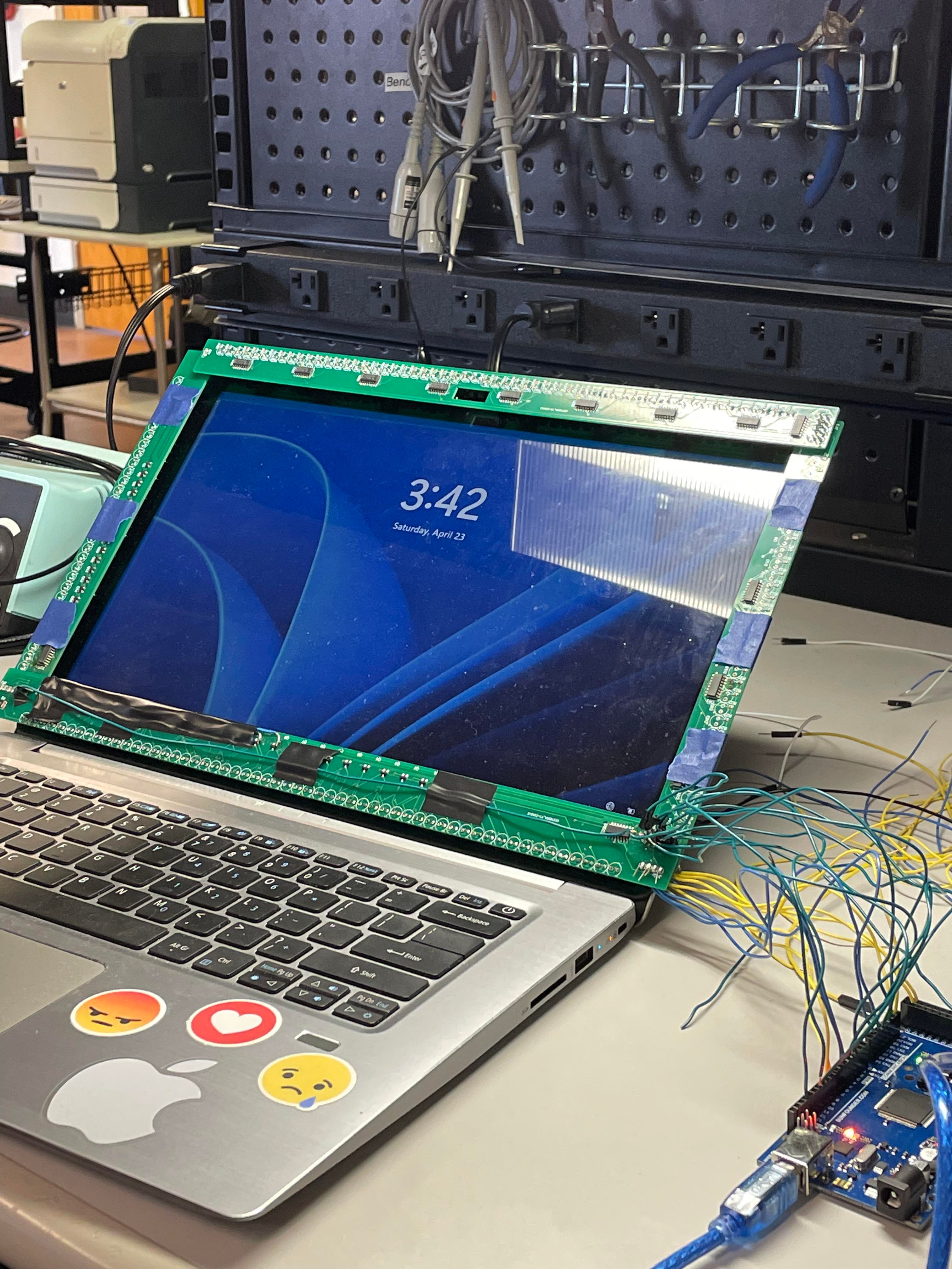
This week, I finalized the hardware. In the picture below, the frame and the Arduino can be seen along with the laptop to be used for the demo. At the moment, we have simply taped the frame onto the screen.
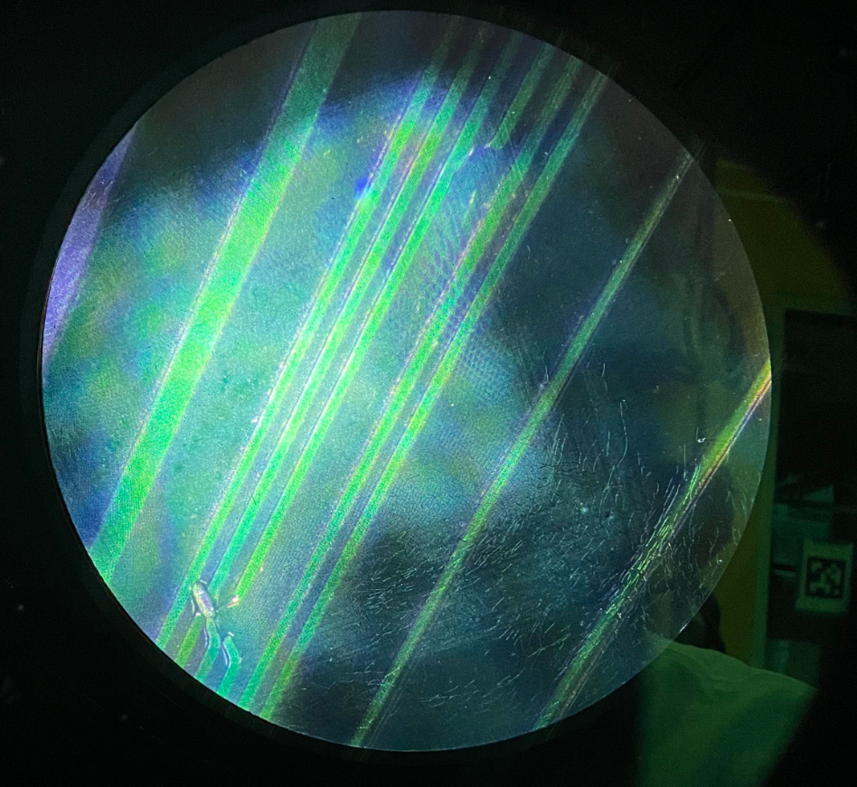
More specifically, I had to work on the long edges this week to complete the frame, as the short edges were tested last week. Unfortunately, after we had already soldered all of our components to the long LED frame, I discovered during testing that JLCPCB had misprinted our board (seen under the microscope below. Fortunately, although there appears to be overlap in the image, there was no short between the wires, so all that was needed was a grueling process of hacking jumper wires between the disconnected nodes. In total, 3 traces needed repair.
I am now officially ahead of schedule, as all of the hardware debugging has been completed. I can now dedicate my focus to helping on the software end. I will mainly work on optimization going forward, as there are several pieces of the code that I know could be accelerated using bit arithmetic. I also may figure out a better way of securing the frame to the laptop than with just tape.
Team Status Report for 4/16
This week, we mainly focused on soldering the new PCBs and hardware testing. Darwin and Matt K worked on scaling up the software to work with the larger frame. There was also work done with regard to improving single-finger gestures. As for the hardware, we are slightly ahead of schedule as the short edges are ready to go without any hacking necessary. We hope to have the same success with the long edges in the coming week.
Next week, we would like to have the frame fully connected so that we can begin testing the software with it. If there are single-bit errors in the top and bottom frames like there were with the side frames, that shouldn’t be much of an issue, as we should still be able to test certain aspects of the code, such as how we are doing with latency and refresh rate.
Thanks to the work we put in this week, we find ourselves about a half-week ahead of schedule going forward.
Matthew Shen’s Status Report for 4/16
This week, I made some very significant progress on the hardware side. Since we finally got the decoders, we were finally able to start testing our design as it will be in its final form. To begin, I wrote an Arduino script that could sweep through the entire left/right diode arrays. While testing, I came across a single bit error, where it appeared as though a photodiode was always receiving light, even when blocked. That is, instead of the anode dropping from 5V to 0V, it would only drop to 3.4V for some reason, which was not enough to force the mux input low. I tried resoldering and replacing its 210k resistor to no avail. Then, I tried replacing the photodiode, after which nothing changed. So, I decided to replace the multiplexer, as that was my last guess as to what could be wrong. This proved to be the issue, as the new mux worked seamlessly.
Another thing I did was start soldering the long (top/bottom) edges of the frame with Darwin. This process is almost complete; all that is left to be done is to solder the photodiodes into the top. As for next week, I will modify my Arduino script to test the top and bottom. Using this script, I will do some hardware debugging. If all the components and circuits work, there may be some time to start integrating the hardware with the screen control, as Matt K has been working on the Python code to transfer the data. In sum, I am at least on schedule. Depending on the functionality of the components on the top/bottom PCBs, I might be ahead of schedule by the end of the coming week.