We are still waiting on our decoders, which are concerningly behind schedule. This week, for our project demo, I reconfigured the breadboard prototype that we used for early-stage testing. We decided to come up with a quick script that could showcase the entire stack of our project, from hardware to serial communication to screen control. The hardware we used only features 7 LEDs, so we drastically upscaled the distance between touches on the screen from the distance on the LEDs. But for our final implementation, we hope to have a 1:1 ratio between the LED separation and how they map to screen touches. We are on schedule to finish in time, although we have slightly less slack time now. This coming week, if the decoders still don’t come in, I may place another order on a different website, or worst case, start trying to hack the correct decoders (which we have, but are through-hole components) onto the SMD pads.
Matthew Shen’s Status Report for 4/3/22
This week was dedicated to PCB construction. Unfortunately, our progress was slowed since I ordered the wrong decoders for our PCB. However, with regards to what was successful, our PCB header pins line up perfectly, so when we solder them in, the frame should be perfectly rectangular. Additionally, when a test was run with the wrong decoders (active low instead of active high), the logic seemed correct in that all of the LEDs that were expected to be on were off and vice-versa. This suggests that once we receive the correct decoders, the particular frame we tested should work as expected. Another thing that went well was the soldering process in general. All of our components fit perfectly on their pads, and the stencil-oven combination has worked flawlessly. This coming week, we hope to get the new decoders on Monday so that we can get at least one pair of edges working for our demo on Wednesday. If that pair of edges functions appropriately, we may try to have the whole frame up and running by Wednesday. My task for this week will mainly be soldering and hardware debugging. We are still on schedule to finish in time.
Matthew Shen’s Status Report for 3/26
Towards the end of this past week, we finally received the parts for the PCB and the PCBs with stencils themselves. One of the tasks I did this week involved running tests to estimate the appropriate resistance needed to be put in series with the LEDs in order to run 100mA current through each diode. When I placed the order, I had ordered a resistor with a quarter the ohmage as the one used in the unit tests with just one LED at a time (since we are illuminating up to 4 100mA diodes at a time). Then, I ordered a couple of resistors with +/- 1.5 Ohms in case the PCB traces introduce more wire resistance than in our tests. Since we only have a couple of these high-power resistors to place, it shouldn’t be too much of a problem to desolder the resistor if it is too resistive or not enough. Additionally, while the LEDs we use are rated for 100mA of constant current, they can theoretically safely handle 1A of current so long as they are pulsed (which is our mode of operation). So, we should be able to run our diodes comfortably with all this in mind. Next week, we will begin soldering and frame assembly. I believe this puts us right on schedule to finish our project in time.
Matthew Shen’s Status Report for 3/19
Over the past couple of weeks, I have focused on finalizing and ordering the PCB. A lot of the PCB work involved designing a way to connect all of our PCBs electrically and mechanically. We intend to kill two birds with one stone by using through-hole connector pins to act as a way to fasten the boards together, while also passing signals from the Arduino along to the top and left edges. Since we have at most 2 tries getting the PCBs right, I spent a significant deal of time verifying the dimensions of these so that we should only have to worry about electrical problems if another iteration is necessary. We are still awaiting the board, but I also have yet to place an order for the through-hole components.
I also purchased solder paste as we have updated our PCB assembly plan to use a PCB stencil and oven to place our components onto the board. I feel like we are on schedule, although the PCB’s arrival will dictate our schedule going forward.
Matthew Shen’s Status Report for 2/26/22
This week, I laid out another PCB for the frame. Additionally, I ran some more thorough tests to determine the rise and fall times of the photodiode sensors. Some updates to our circuit were also made to try to optimize it for speed. Since the photodiodes are attached to very large resistors, (now 200 kOhm down from 300 kOhm) the time constants are actually non-negligible. With the 200 kOhm resistors along with the 370 pF input capacitance of the MOSFET buffers and 18 pF for the photodiode capacitance, this equates to a time constant of 77.6 microseconds. Realistically, if we were to use a MOSFET buffer stage for our final implementation, the input capacitance wouldn’t need to be nearly this large, but since these FETs were all I had on hand, I needed to make do with them. When tested under the scope, it seemed like the rise and fall times were actually closer to 72 us, but it was useful to see that the hand calculations were very much in the ballpark of reality.
As for changes to our circuit, we have opted to remove the MOSFET buffer stage. After talking to Dr. Fedder about the issue mentioned in last week’s status report, we realized that the muxes were likely designed with NPN transistors, which was an accidental purchase on my part. I ordered CMOS multiplexers this week, which should allow us to feed the anodes of the photodiodes directly into the mux inputs. Another enormous benefit is that the input capacitance of these CMOS muxes is around only 10 pF. Assuming the continued consistency of my hand calculations, this would equate to a time constant of around 5.6 us. What this means is that a single sweep for the entire array of LEDs/photodiodes could theoretically take just 170 us. That means it will take less time to sweep the photodiodes than it will take to send that data to the computer over USB-serial, which is great news for our design requirements.
In the coming week, I hope to have our PCBs ready to order with the hope that they will arrive by the end of spring break. I will also test our updated circuit plan when the muxes arrive.
Matthew Shen’s Status Report for 2/19
Towards the beginning of the week, we were still waiting for our parts to arrive. So, I started off by designing a PCB for the bottom side of our frame, which contains an array of 56 IR LEDs. The LEDs are turned on in groups of 4, where every 14th diode is turned on at the same time. We use two 3:8 decoders (only using 7 outputs from each) to turn on a power MOSFET that allows current to flow through the correct set of LEDs. On the far right-hand side, we have allocated space for through-holes for I/O and power supply from the external Arduino.
Shown below are, from top to bottom, an overhead, an underside, and a 3D view of the PCB.


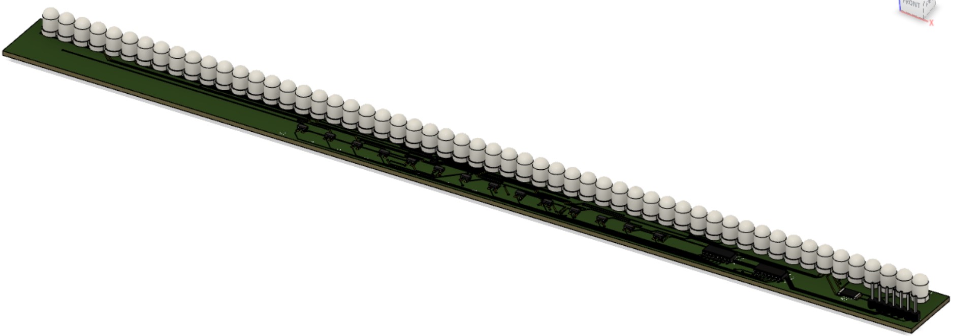 Edits may be made to add a ground plane. For our purposes, we won’t actually be inserting header pins and the LEDs will be oriented parallel to the PCB surface. We have yet to decide which side of the PCB we want the LEDs to protrude from.
When the parts arrived, the next step was to create one “segment” of our LED-Photodiode array. This involved creating an array of just 7 LEDs/Photodiodes and using only one decoder and one mux to select the correct inputs. The breadboarded circuit is shown below (emitters on top, photodiodes on bottom):
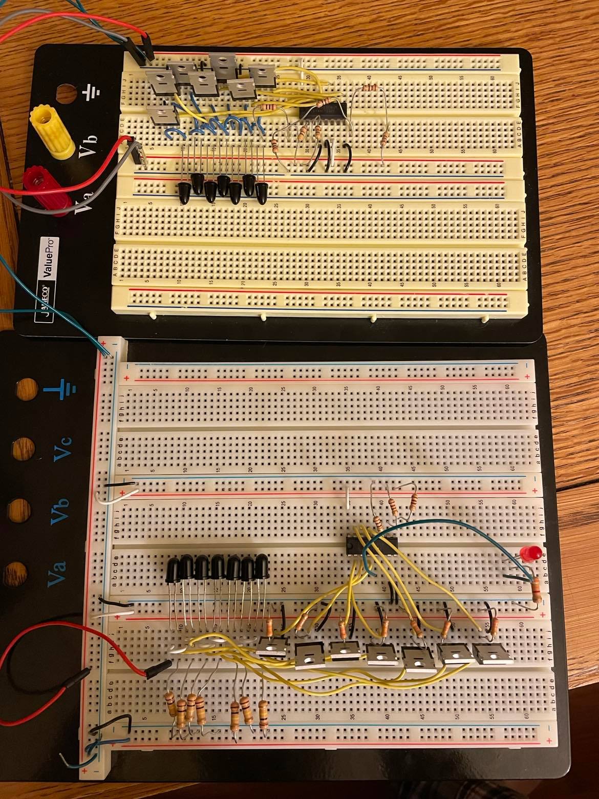
Throughout the verification of this circuit, there was one issue. Initially, the cathodes of the photodiodes were connected directly to the inputs of the multiplexer. However, there was unusual behavior when the light was blocked from entering the diode; for a still-unknown reason, instead of the voltage dropping to near-zero as expected, the voltage at this node would settle around 1.7 V. The voltage would still drop to 0 when not connected to the mux input. Fortunately, I had extra MOSFETs on hand, so I used these as buffers between the photodiodes and the mux inputs. This method removed the unusual 1.7 V at this node.
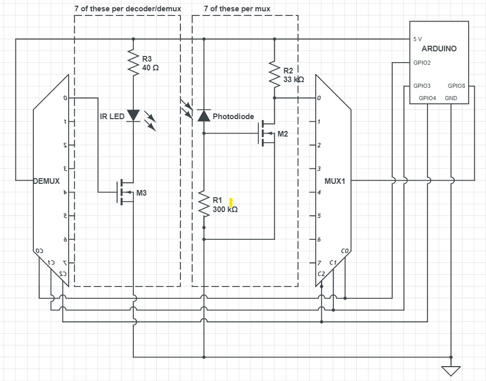
Below is a schematic of the above image, with repetitive elements removed:
Matt Shen’s Status Report for 2/12/22
For this week, my main task was circuit design and product purchasing based on the design.
List of components so far:
- IR Photodiode, 5mm-wide
- IR LED, 5mm-wide
- one with 6° viewing angle, 300 mW/sr
- another with 10° viewing angle, 550 mW/sr
- 3:8 Decoder, active-high
- 8:1 Multiplexer
- Power MOSFET, N-type
- Arduino Mega
Resistors are also shown below, but the ideal values for the design are yet to be determined. The diodes in black are photodiodes and in red are the IR LEDs. For the array of photodiodes, the cathodes are attached to the 5V pin of the Arduino. The anodes are each equipped with a pull-down resistor; each of these nodes is also hooked up to a Multiplexer’s input ports. The multiplexer then feeds either a high or low signal to an Arduino’s read pin. The photodiode being read from is selected by control pins from the Arduino. One potential issue that could arise from this design involves a limitation of the mux; with a VIL & VIH of 0.8 V & 2.0 V respectively, any values in the range of 0.8-2.0 V could cause errors. If this proves to be an issue in our breadboard tests, our first plan of action would be to add a single-MOSFET buffer in between each PDN and the Multiplexer.
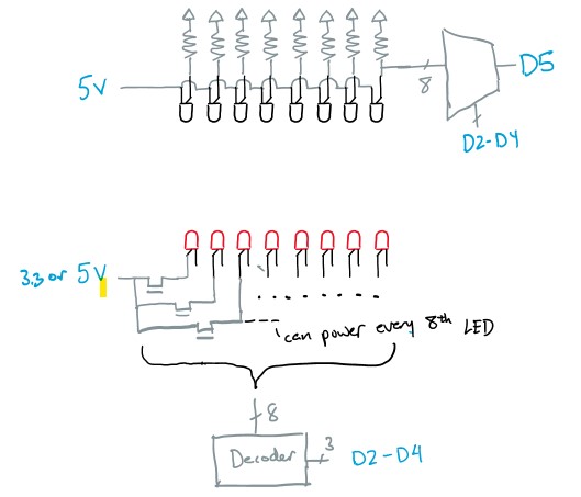
For the LED array, we will use the same control pins for the mux to control the decoder. This decoder will instruct a power MOSFET to turn on its LEDs. We will also need resistors (not shown) for current limiting. For our diodes to work as desired, we need 100mA of current through them. In order to conserve power, we will try to have pairs of LEDs stacked on one another if the drain-source voltage of the MOSFET and on voltages of the LEDs permit enough headroom.
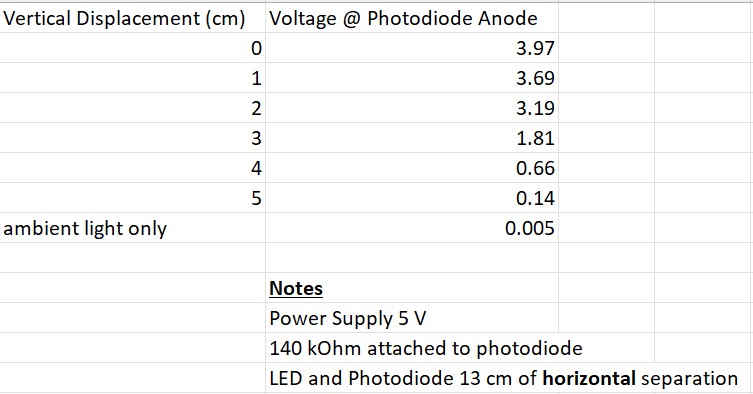
Finally, I also ran some tests this week to get a sense of how neighboring LEDs might interfere with light detection. These tests were done with a random IR photodiode, so we won’t put too much weight on them. We used the aforementioned 6° LED as well.
With regards to the timeline, I accomplished everything as was planned for this week, but nothing more. However, since our new implementation idea removes the need for a software simulation, I think we are slightly ahead of schedule. For next week, if we can get the parts before the next status update, it would be ideal to layout the circuit shown above and get it to interface with a Python-controlled Arduino. In the meantime, I will begin designing a PCB to get a sense of how much space our implementation will need.