Darwin Torres’ Status Report for 2/26/2022
This week, I made additional changes to the screen control interface. Previously, the main functionality that was added was the ability to send a request to the OS to emulate a touch tap. That is, given a pair of (x,y) coordinates, we emulate a finger pressing down and then immediately lifting up. However, these two steps are actually separate events that are sent to the OS – finger down, finger up – we just combined them into one quick event. If an extended period of time passes before “finger up”, Windows applications can register this as a finger hold. Thus, changes had to made so that we can support these touch-specific gestures. This was done by updating the interface to support three requests to the OS: finger down, finger up, and update position. The “update position” allows us to change the position of the finger while it is down, simulating a drag. These requests have been tested using a test script in python and result in successful calls individually, however the drag mechanism still needs to be ironed out. Overall, everything is going according to schedule, and I hope to conduct more testing in the coming weeks as we move on to integration between the hardware, Arduino, and Windows. Once integrated, we can conduct better tests as we will be able to use our fingers to directly interact with the UI. Unfortunately, current tests do not tell us much about usability as everything is simulated without physical interaction, so I am excited about these future steps.
Team Status Report for 2/26/22
Our biggest goal right now is to finish all of the PCB development and order the PCBs before spring break so that we can begin soldering and testing with the actual PCB once classes resume. If this is not completed before break, it is going to cost us about two weeks, so we are considering this the biggest risk to our project right now. We plan to have all three group members working on this task next week to ensure that it is completed.
Overall, no major changes have been made to the design. If anything, the biggest change is the choice to move away from the pyFirmata library for the Arduino-Python interface and to the serial library. This change was necessary due to the fact that each photodiode needed 10ms to be read, which will be far too slow for MVP goal. Moving forward, we will test different baud rates with the serial library to see how fast the system can perform.
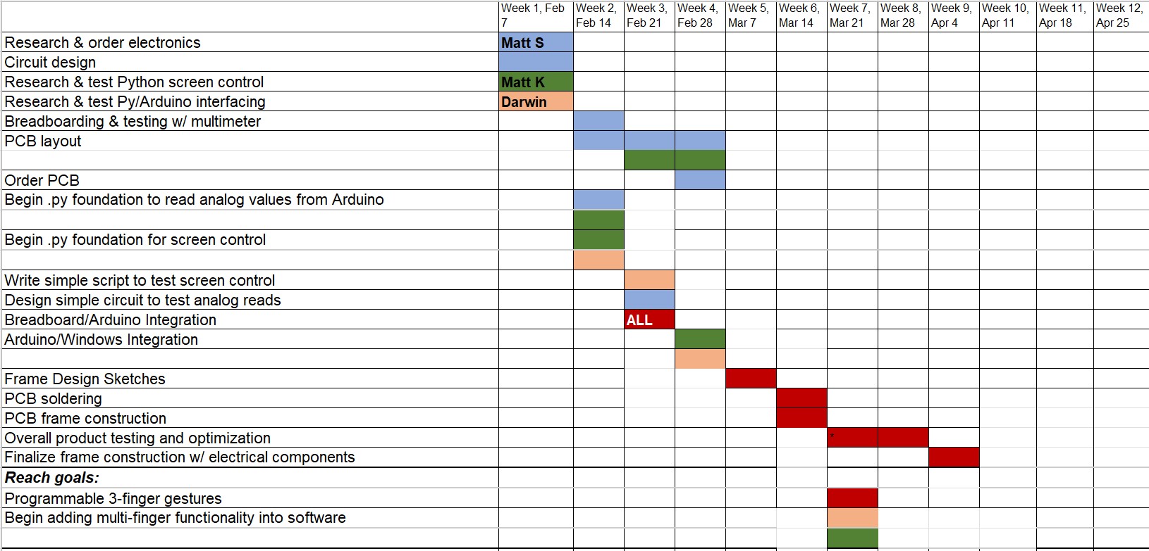
Right now, the schedule remains the same since we are keeping up with the tasks on our Gantt chart. Overall, we feel that we have been making good progress and our project is on task to be completed successfully.
Matthew Kuczynski’s Status Report for 2/26/22
This week I continued my progress with the Python-Arduino interface and worked on routing the PCBs. Last week, I learned that the pyFirmata interface that we intended to use would not be fast enough to loop over all of the LEDs, so I spent a large portion of this work exploring alternative options. Eventually, I discovered that uploading the code that loops over the select line values to the Arduino is unsurprisingly much faster than using pyFirmata. In order to read the values from the Arduino, I developed a script using the Python serial library that did string parsing to get the digital values and the select value. The PCB routing task proved to be tough due to width of the PCB, and the Auto-router was unable to complete the task on its own. While some of the PCBs have been completed, the task remains ongoing. Overall, I think that I am on schedule since I am keeping up with the tasks in the Gantt chart. Next week, I plan to continue working on PCB layout and the breadboard-Arduino integration.
![]()
Matthew Shen’s Status Report for 2/26/22
This week, I laid out another PCB for the frame. Additionally, I ran some more thorough tests to determine the rise and fall times of the photodiode sensors. Some updates to our circuit were also made to try to optimize it for speed. Since the photodiodes are attached to very large resistors, (now 200 kOhm down from 300 kOhm) the time constants are actually non-negligible. With the 200 kOhm resistors along with the 370 pF input capacitance of the MOSFET buffers and 18 pF for the photodiode capacitance, this equates to a time constant of 77.6 microseconds. Realistically, if we were to use a MOSFET buffer stage for our final implementation, the input capacitance wouldn’t need to be nearly this large, but since these FETs were all I had on hand, I needed to make do with them. When tested under the scope, it seemed like the rise and fall times were actually closer to 72 us, but it was useful to see that the hand calculations were very much in the ballpark of reality.
As for changes to our circuit, we have opted to remove the MOSFET buffer stage. After talking to Dr. Fedder about the issue mentioned in last week’s status report, we realized that the muxes were likely designed with NPN transistors, which was an accidental purchase on my part. I ordered CMOS multiplexers this week, which should allow us to feed the anodes of the photodiodes directly into the mux inputs. Another enormous benefit is that the input capacitance of these CMOS muxes is around only 10 pF. Assuming the continued consistency of my hand calculations, this would equate to a time constant of around 5.6 us. What this means is that a single sweep for the entire array of LEDs/photodiodes could theoretically take just 170 us. That means it will take less time to sweep the photodiodes than it will take to send that data to the computer over USB-serial, which is great news for our design requirements.
In the coming week, I hope to have our PCBs ready to order with the hope that they will arrive by the end of spring break. I will also test our updated circuit plan when the muxes arrive.
Darwin Torres’ Status Report for 2/19/22
This week, I continued with developing the screen control interface. Originally, we were going to register taps detected with our sensors as mouse clicks using one of the libraries mentioned last week. However, we found that we can instead send touch control requests using Microsoft’s Win32 C++ API. We are still using Python, but taking advantage of the builtin ctypes library to create wrappers that directly call the Win32 C++ functions. The provided methods for touch manipulation support not only single taps, but also drag and multi-touch gestures, unlike the cursor-control libraries we were looking at before. This makes it more intuitive to add support beyond single-contact touches. I developed a simple interface for emulating a tap at a pair of (x,y) coordinates and testing found that the tap was successful and perceivably instantaneous. Libraries such as PyAutoGUI can take up to hundreds of milliseconds to complete a single mouse-click which would hurt the user experience. Using this new method, a touch was registered in less than a millisecond, giving us more room to work with on the hardware side as we work toward a goal of an overall response time of less than ~150ms. Overall, I am ahead of schedule, giving me time to test out simulating drag and learn more about the additional capabilities of the API. Next week, I will help in starting the breadboard/Arduino integration, while also possibly being able to start the Windows integration early in our schedule.
Matthew Kuczynski’s Status Report for 2/19
This week, my main task was to develop and debug the Arduino software that could recognize the basic touch functionality. As explained last week, I chose to use the pyFirmata library to interface the Arduino with Python, so I started the week by preparing the software for actual testing later in the week. Once the parts order came in, Matt S. was able to build a circuit that we connected to the Arduino Mega, so that the software could be tested. As expected, there were many issues with the software that I had developed at the start of the week, so the later part of the week was mostly spent debugging. One struggle that I faced was learning how to use a pyFirmata iterator, which is built in to the pyFirmata library. At least to me, it was unclear that the iterator was necessary for the functionality that we needed, but once I properly added it to the code many problems were solved. The other large issue was that the time between writing the select line and reading the output was not large enough, so seemingly random values were being sent back to the Python code. For now, about 10 ms are needed in order for the values to be accurate, however we will need this to be faster in order to reach our MVP goal since we will need to loop over all of the LEDs. I feel that I am on schedule since I kept up with my Gantt chart goal this week. Next week, I will aim to help Matt S. with the PCB layout, work on frame sketches, and work on the Breadboard/Arduino integration.
Team Status Report for 2/19/22
This week, we tried to do some preliminary, small-scale testing of our idea. We made a small circuit and tested it with an Arduino. A couple of design changes we made involved how we plan to capture Python data. While Matt K initially experimented with controlling the Arduino with Pyfirmata, this proved to be an unreliable method of rapid data collection. Going forward, we will need an implementation that has data collection already programmed onto the Arduino, and simply use Python to receive the data over USB-serial. One other change we made was that, as we discussed as a possibility from last week, we needed to add a MOSFET buffer between the Photodiode and the Mux.
As for schedule changes, the hardware side is moving at the expected pace, and we hope to have PCBs ready to order by the beginning of March. The software side of things is moving okay, although we still haven’t made the for-certain determination that Python will be fast enough. But, from all of our Python tests so far, we have not encountered anything problematic enough to transition to C++.
Matthew Shen’s Status Report for 2/19
Towards the beginning of the week, we were still waiting for our parts to arrive. So, I started off by designing a PCB for the bottom side of our frame, which contains an array of 56 IR LEDs. The LEDs are turned on in groups of 4, where every 14th diode is turned on at the same time. We use two 3:8 decoders (only using 7 outputs from each) to turn on a power MOSFET that allows current to flow through the correct set of LEDs. On the far right-hand side, we have allocated space for through-holes for I/O and power supply from the external Arduino.
Shown below are, from top to bottom, an overhead, an underside, and a 3D view of the PCB.


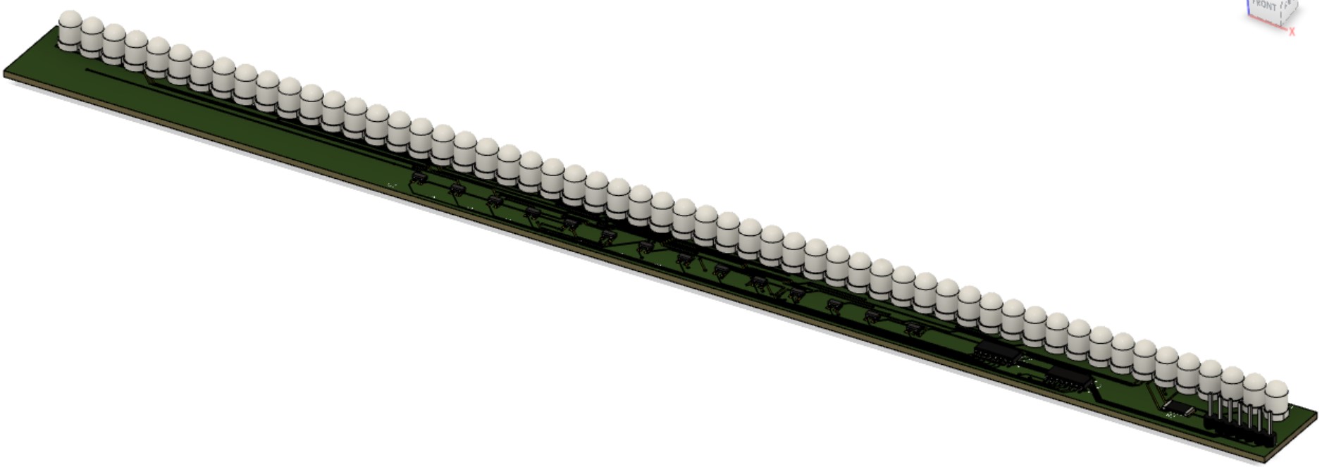 Edits may be made to add a ground plane. For our purposes, we won’t actually be inserting header pins and the LEDs will be oriented parallel to the PCB surface. We have yet to decide which side of the PCB we want the LEDs to protrude from.
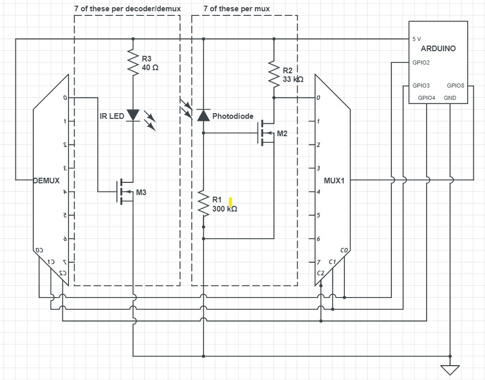
When the parts arrived, the next step was to create one “segment” of our LED-Photodiode array. This involved creating an array of just 7 LEDs/Photodiodes and using only one decoder and one mux to select the correct inputs. The breadboarded circuit is shown below (emitters on top, photodiodes on bottom):
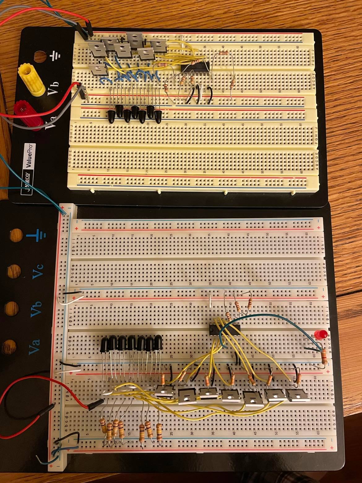
Throughout the verification of this circuit, there was one issue. Initially, the cathodes of the photodiodes were connected directly to the inputs of the multiplexer. However, there was unusual behavior when the light was blocked from entering the diode; for a still-unknown reason, instead of the voltage dropping to near-zero as expected, the voltage at this node would settle around 1.7 V. The voltage would still drop to 0 when not connected to the mux input. Fortunately, I had extra MOSFETs on hand, so I used these as buffers between the photodiodes and the mux inputs. This method removed the unusual 1.7 V at this node.
Below is a schematic of the above image, with repetitive elements removed:
Darwin Torres’ Status Report for 2/12/22
This week, I conducted research on how to interface with Windows to register our screen taps as mouse clicks. I have begun exploring different Python libraries and have narrowed down our choices to the following:
- pywin32
- PyAutoGUI
- mouse
As of right now, the main focus is to create demos to test each library and compare their performance, ease-of-use, and compatibility. Originally, I was going to create a simulation to test different configurations of our original analog design, but as we have updated our approach, this was no longer necessary, which allowed me to get ahead of schedule and move to this step. This weekend, in addition to developing the demos for each library, I plan to create an interface that would allow us to switch between each library, allowing for easier integration with my team’s code as we test out our screen control software and decide on which library is best.