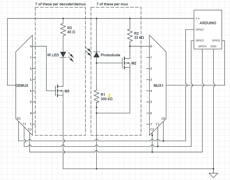
Towards the beginning of the week, we were still waiting for our parts to arrive. So, I started off by designing a PCB for the bottom side of our frame, which contains an array of 56 IR LEDs. The LEDs are turned on in groups of 4, where every 14th diode is turned on at the same time. We use two 3:8 decoders (only using 7 outputs from each) to turn on a power MOSFET that allows current to flow through the correct set of LEDs. On the far right-hand side, we have allocated space for through-holes for I/O and power supply from the external Arduino.
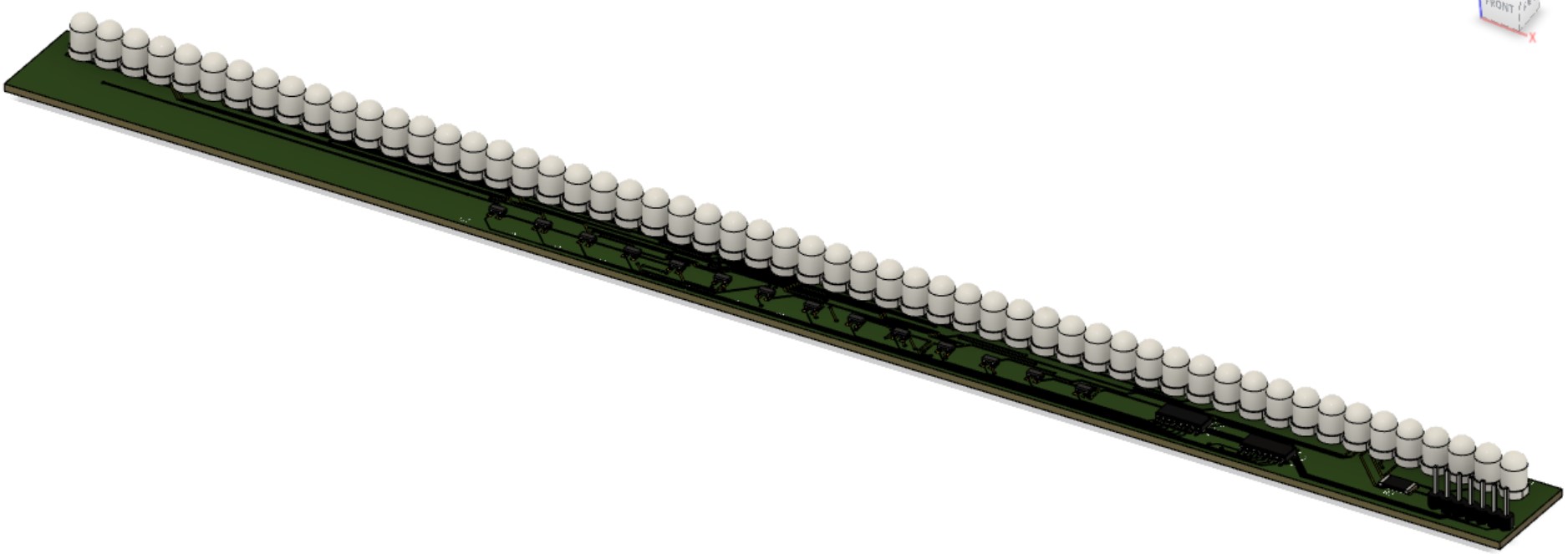
Shown below are, from top to bottom, an overhead, an underside, and a 3D view of the PCB.


 Edits may be made to add a ground plane. For our purposes, we won’t actually be inserting header pins and the LEDs will be oriented parallel to the PCB surface. We have yet to decide which side of the PCB we want the LEDs to protrude from.
When the parts arrived, the next step was to create one “segment” of our LED-Photodiode array. This involved creating an array of just 7 LEDs/Photodiodes and using only one decoder and one mux to select the correct inputs. The breadboarded circuit is shown below (emitters on top, photodiodes on bottom):
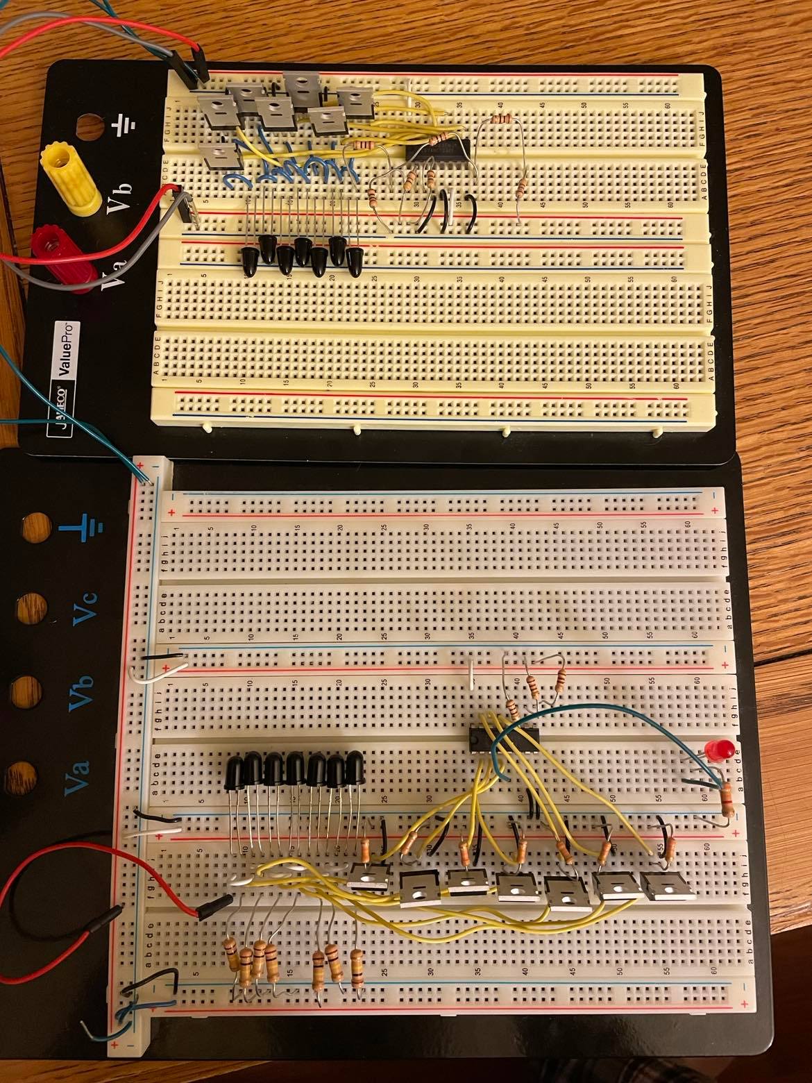
Throughout the verification of this circuit, there was one issue. Initially, the cathodes of the photodiodes were connected directly to the inputs of the multiplexer. However, there was unusual behavior when the light was blocked from entering the diode; for a still-unknown reason, instead of the voltage dropping to near-zero as expected, the voltage at this node would settle around 1.7 V. The voltage would still drop to 0 when not connected to the mux input. Fortunately, I had extra MOSFETs on hand, so I used these as buffers between the photodiodes and the mux inputs. This method removed the unusual 1.7 V at this node.
Below is a schematic of the above image, with repetitive elements removed: