For this week, my main task was circuit design and product purchasing based on the design.
List of components so far:
- IR Photodiode, 5mm-wide
- IR LED, 5mm-wide
- one with 6° viewing angle, 300 mW/sr
- another with 10° viewing angle, 550 mW/sr
- 3:8 Decoder, active-high
- 8:1 Multiplexer
- Power MOSFET, N-type
- Arduino Mega
Resistors are also shown below, but the ideal values for the design are yet to be determined. The diodes in black are photodiodes and in red are the IR LEDs. For the array of photodiodes, the cathodes are attached to the 5V pin of the Arduino. The anodes are each equipped with a pull-down resistor; each of these nodes is also hooked up to a Multiplexer’s input ports. The multiplexer then feeds either a high or low signal to an Arduino’s read pin. The photodiode being read from is selected by control pins from the Arduino. One potential issue that could arise from this design involves a limitation of the mux; with a VIL & VIH of 0.8 V & 2.0 V respectively, any values in the range of 0.8-2.0 V could cause errors. If this proves to be an issue in our breadboard tests, our first plan of action would be to add a single-MOSFET buffer in between each PDN and the Multiplexer.
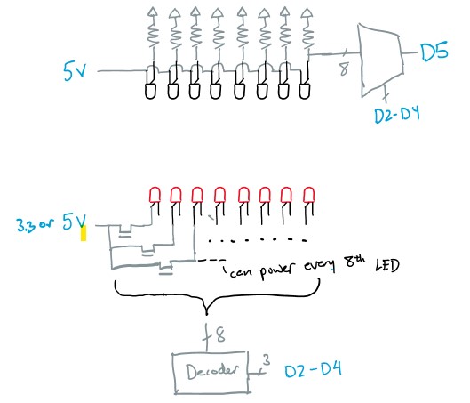
For the LED array, we will use the same control pins for the mux to control the decoder. This decoder will instruct a power MOSFET to turn on its LEDs. We will also need resistors (not shown) for current limiting. For our diodes to work as desired, we need 100mA of current through them. In order to conserve power, we will try to have pairs of LEDs stacked on one another if the drain-source voltage of the MOSFET and on voltages of the LEDs permit enough headroom.
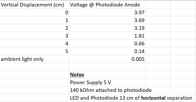
Finally, I also ran some tests this week to get a sense of how neighboring LEDs might interfere with light detection. These tests were done with a random IR photodiode, so we won’t put too much weight on them. We used the aforementioned 6° LED as well.
With regards to the timeline, I accomplished everything as was planned for this week, but nothing more. However, since our new implementation idea removes the need for a software simulation, I think we are slightly ahead of schedule. For next week, if we can get the parts before the next status update, it would be ideal to layout the circuit shown above and get it to interface with a Python-controlled Arduino. In the meantime, I will begin designing a PCB to get a sense of how much space our implementation will need.