Chakara’s Status Update for 05/03/2020

This week, I mainly helped our team prepared for the final presentation. I then started to help the team write our video script and recorded audio files for the overview and triangulation section.

After giving some feedback to Jeremy for video and animations, I mainly worked on the final report. I am currently drafting up the final report for Alex and Jeremy to fill in their parts and proofread the final thing.

I am currently on schedule and hope to finish the final report by the deadline.

Chakara’s Status Update for 04/26/2020

This week I started of by helping Alex write the verification script.

After seeing results from different objects,  we realized the triangulation, although looks good, doesn’t give satisfiable results. I spent a lot of time fixing the triangulation algorithm. The Screened Poisson algorithm was working decently well and was fast, but using our metrics to test points from our resulting meshes to the ground truth meshes, our accuracy was not as good. Also, there were a few points that were outside of 5% of the longest axis of the ground truth model which means we failed our accuracy requirement.

I then switched back to our Delaunay Triangulation algorithm from pyvista. I adjusted different parameters. Although this algorithm takes so much longer, the accuracy results were much more satisfiable. The time was around 3-4 times longer than Poisson algorithm for most meshes but was still within our timing requirement. No points were outside of 5% of the longest axis of the ground truth model and only a few points were outside of 2% of the longest axis of ground truth models.

After fixing everything, I worked with Alex to write our driver. We added different parameters to the script so that we can adjust different parameters and test our pipeline more efficiently. This also helps with when we are trying to look into tradeoffs and validation for the final presentation and final report. Users can also then use our program by just running this driver script. Moreover, I also helped write the driver to be able to output the results in CSV format for easier analysis.

After that, I worked together with both Jeremy and Alex in creating the final presentation slides so that we can show different tradeoffs and our whole project.

I’m currently on schedule and next week, I hope to work with both Jeremy and Alex to finish the final report and the two videos.

Chakara’s Status Update for 04/19/2020

This week, on top of working with other team members on preparing for the in-lab demo and thinking of different testing we could perform, I mainly worked on improving the triangulation algorithm. As mentioned in last week’s report, the triangulated meshes using different algorithms were not satisfiable. The Screened Poisson Reconstruction proposed in Kazhdan and Hoppe’s paper looked the most promising; thus I decided to try fixing it. 


I first tried working on other example pcd files from the web, and the Poisson Reconstruction algorithm worked perfectly. 

I looked deeper into the pcd files and the only two main differences were just that example pcd files also contain FIELDS normal_x, normal_y, and normal_z which have normals information. Thus, my speculation was correct. 


I then tried orienting the normals to align with the direction of the camera position and laser position but they still didn’t work. 


After that, I tried adjusting the search parameter when estimating the normals. I changed from the default search tree to o3d.geometry.KDTreeSearchParamHybrid which I can adjust the number of neighbors and the radius size to look at when estimating the normals for each point in the point cloud. After estimating the normals, I then orient the normals such that the normals are all pointing inward and invert the normals out so that all the normals are pointing directly outward from the surface. The results are much more promising. The smoothed results were not as accurate so I decided to ignore smoothing. 

I then realigned the normals to get rid of the weird vase shape by making sure that the z-axis alignment of the normals was at the center of the point cloud. 

After that, I helped Alex work on the verification by writing a function to get the accuracy percentage. I used Alex’s work on getting the distances between the target and the source and wrote a simple function to check if 90% of the points are within 5% of the longest axis and 100% of the points are within 2% of the longest axis. 

I am currently on schedule. For next week, I hope to fully finish verification and help the team prepare for the final presentation and demo videos. 

Chakara’s Status Update for 04/11/2020

This week, after Alex made fixes to the point cloud construction algorithm, I tried testing the new pcd files on our current triangulation algorithm. The rendered object looks perfect.

However, testing a more complicated object such as a monkey, the triangle meshes look a little rough and might not meet our accuracy requirements. 

I looked into the point cloud and it is very detailed so the problem is with the delaunay technique we are currently using. Although I tried changing different parameters, the results are still not satisfiable. 

Thus, I started looking into other libraries which might have other techniques. I ended up trying open3d this week. The first technique I try is to compute a convex hull of the point cloud and generate a mesh from that, the result is very not satisfiable since the convex hull is just a set of points is defined as the smallest convex polygon, that encloses all of the points in the set. Thus, it only creates an outer rough polygon surface of the monkey. 

After that, I tried the pivoting ball technique. This implements the Ball Pivoting algorithm proposed in F. Bernardini et al. The surface reconstruction is done by rolling a ball with a given radius over the point cloud, whenever the ball touches three points a triangle is created, and I could adjust the radii of the ball that are used for the surface reconstruction. I computed the radii by finding the norms of all the closest distance between every point in the point cloud and multiply it by a constant. Using a constant smaller than 5, the results were not satisfiable. The results got more accurate as I increased the constant size; however, a constant above 15 takes longer than 5 minutes to compute using my computer which would not pass our efficiency requirement, and the results were still not as satisfiable as I hoped for. I tried different smoothing techniques but they did not help much. 

The next technique I used was the poisson technique. This implements the Screened Poisson Reconstruction proposed in Kazhdan and Hoppe. From this method, I can vary the depth, width, scale, and the linear fit of the algorithm. The depth is the maximum depth of the tree that will be used for surface reconstruction. The width specifies the target width of the finest level octree cells. The scale specifies the ratio between the diameter of the cube used for reconstruction and the diameter of the samples’ bounding cube. And linear fit can tell if the reconstructor uses linear interpolation to estimate the positions of iso-vertices or not. 

The results are accurate and look smooth once I normalize the normals but there is a weird surface. By looking at the pcd file and a voxel grid (below), there are no points where this weird rectangular surface lies. 

Currently, I assumed that the weird surface is from the directions the normals are oriented to, since the location of the surface changes when I orient the normals differently.

I’m currently a little behind schedule since I hoped to fully finish triangulation, but luckily, our team allocated enough slack time for me to fix this. If I finish early, I hope to help the team work on the testing benchmarks and adding noise.  

For next week, I hope to be able to fix this issue, either by applying different other techniques on top of the poisson technique or changing to marching cubes algorithm which also seems probable.

Chakara’s Status Update for 04/04/2020

This week, I mainly worked on integrating my triangulation work with Alex and Jeremy’s work. From the global point cloud Alex constructed, I needed to fine-tune a few different parameters for the triangulation module to work properly. Below are the point cloud images from 2 different perspectives. 

The initial mesh looks like this. 

After adjusting the parameters (mainly the distance value to control the output of this filter and the tolerance to control discarding of closely spaced points), we achieve the results below. 

I’m currently on schedule as our team mainly focused on how to most appropriately demo our project. 

For next week, I hope to fine-tune the triangulation algorithm and help Alex finish writing the testing benchmarks. I also hope to help the team add noise to our input data.

Chakara’s Status Update for 03/28/2020

This week, I spent more time understanding different algorithms in our software pipeline. I mostly work on triangulation, converting point clouds to triangular meshes. The actual implementation of triangulation is very complicated, especially for 3D objects. Thus, I decided to search for different libraries and modules that would fit our project scope best (which is also according to our design). I decided to use pyvista because it is a well-supported library and can provide VTK which helps with the project.

Below are examples of my work converting generated sample point clouds to triangular meshes.

For the plane object, we can see that there are 2 meshes, one is completely inaccurate while the other is a bit more accurate. This depends on different parameters I have to adjust: distance value to control the output of this filter, tolerance to control discarding of closely spaced points, and multiplier to control the size of the initial, bounding Delaunay triangulation.

This would most likely be the main risk and complicated part of this algorithm, figuring global parameters that would work well for all objects to meet our requirements.

I’m currently on schedule.

Next week, I hope to fine-tune this algorithm more to work with multiple objects. I also hope to integrate my part with Alex’s to test if the algorithm works on our objects. I also hope to start working on the test benchmarks and prepare for the demo.

Chakara’s Status Update for 03/21/2020

This week, I spent the first half of the week traveling back to Bangkok and setting up so I did not have much time to work on the project. After meeting with Joe and Professor Tamal on Wednesday, our team would be removing the physical parts of the project and would be creating a simulation of sensor data instead. Since my main tasks of this project were all related to the physical components (rotational mechanism, circuits, platform assembly, etc), our team changed our task delegation. I would now be working closely with Alex to implement different algorithms as needed. As I only understood briefly of our algorithms, I spent this week trying to learn and understand more about them. I also worked on SOW with other team members and was responsible for updating our task list and gantt chart. 

We are currently behind schedule because of the situation of the Coronavirus outbreak. However, after this next week, we hope to catch up on our process since we’re replacing all the physical parts and calibration mechanism with simulated data. 

By next week, I hope to fully understand the main algorithms we would be using and help Alex write some parts of the code related to the testing benchmarks and algorithm to construct global point cloud from sensor data. This would also depend on the data Jeremy would be able to simulate.

Chakara’s Status Update for 03/07/2020

This week I mainly was responsible for picking up different project components and making sure they work as they are supposed to. Below is a summary table of the components that arrived and have been tested. For most mechanical components, we just tested whether or not they are fragile, rotate as they are supposed to, etc. The laser is shown to have enough intensity and the camera capture quality is great. The laser is also class 3A, but as suggested by Professor Tamal, I still contacted CMU to make sure that we don’t need additional training or safety requirements or the laser (which we do not).


Ordered Arrived Tested Item
Yes Yes Nema 23 Stepper Motor
Yes Yes Yes 15 Inch Wooden Circle by Woodpeckers
Yes Yes Yes Swivel Turntable Lazy Susan Heavy Duty Aluminium Alloy Rotating Bearing Turntable Round Dining Table Smooth Swivel Plate for Kaleidoscopes Tabletop Serving Trade Show Displays(10 inch)
Yes Yes Yes Source One LLC 1/8 th Inch Thick 12 x 12 Inches Acrylic Plexiglass Sheet, Clear
Shaft’s Gear
Yes Yes STEPPERONLINE CNC Stepper Motor Driver 1.0-4.2A 20-50VDC 1/128 Micro-step Resolutions for Nema 17 and 23 Stepper Motor
Yes Yes Yes Lazy Dog Warehouse Neoprene Sponge Foam Rubber Sheet Rolls 15in x 60in (1/8in Thick)
Yes Yes ~ Adafruit Line Laser Diode (1057)
Yes Yes Yes Webcamera usb 8MP 5-50mm Varifocal Lens USB Camera Sony IMX179 Sensor,Webcam Support 3264X2448@15fps,UVC Compliant Webcamera Support Most OS,Focus Adjustable USB with Cameras,High Speed USB2.0 Webcams
Yes Nvidia Jetson Nano Developer Kit
Yes Yes Yes 256GB EVO Select Memory Card and Sabrent SuperSpeed 2-Slot USB 3.0 Flash Memory Card Reader


The main part that I tried to test were the motor and the driver board, but I didn’t want to potentially burn them, so I decided to wait until our Jetson arrives or when we borrow an Arduino with a potential mini breadboard and potentiometer (to make sure that the current going to the driver and motor are as specified by their specs). 


On top of this, I did more research on how to connect the motor and driver together and read more articles which use Jetson to control a stepper motor (although different models and drivers). I also talked to TechSparks about the use of their space. I would have to 3D print a gear on the shaft of the motor and all we need to do is create an STL file and estimate how many grams of 3D-printed material we would need. For the laser cutting part, I am not trained. However, I reached out to a friend outside of this class who is trained for laser-cutting and he agreed to help cut out our acrylic sheet to create our internal gear. 


I am currently on schedule. Luckily the parts arrived earlier than we expected even though our team ordered them a few days later than what we planned to. 


For next week, I would mostly be outside of the US for spring break. I would probably not be working on this project until I come back. When I come back, I hope to test out the motor and driver and start assembling the platform together so that Jeremy and Alex can see how the rotational mechanism affects the data capturing and see what adjustments we would have to make. 

Chakara’s Status Update for 2/29/2020

This week, I was mainly working on the Design Review. I was responsible for the main platform design and rotational mechanism. On top of working in parallel with other team members on the Design Review Presentation and Design Document, I was mainly responsible for ordering project components. From the Design Review Presentation, we did a tradeoff analysis and ended up with different project components that we need. From that, I started doing research on different suppliers and models of the components we need to get the most cost-efficient ones while getting the most appropriate shipping time. Below is a table of the project components we ordered this week.


Ordered Item Quantity Unit Price Total Price Shipping Cost Total Cost Description Expected Shipping
Yes Nema 23 Stepper Motor 1 $23.99 $23.99 $0.00 $23.99 2 Days
Yes 15 Inch Wooden Circle  1 $14.99 $14.99 $0.00 $14.99 Plywood for platform 2 Days
Yes Lazy Susan Bearing 1 $27.19 $27.19 $0.00 $27.19 2 Days
Yes Acrylic Plexiglass Sheet, Clear 1 $9.98 $9.98 $0.00 $9.98 Laser cutting for Internal Gear 2 Days
Yes STEPPERONLINE CNC Stepper Motor Driver  1 $38.99 $38.99 $0.00 $38.99 Motor Step Driver 2 Days
Yes Neoprene Sponge Foam Rubber Sheet  1 $14.80 $14.80 $0.00 $14.80 High-friction surface 2 Days
Yes Adafruit Line Laser Diode (1057) 1 $8.95 $8.95 $8.99 $17.94 Projected Laser Stripe 2 Days
Yes Webcamera usb 8MP 5-50mm Varifocal Lens  1 $76.00 $76.00 $0.00 $76.00 2 Days
Yes Nvidia Jetson Nano Developer Kit 1 $99.00 $99.00 $18.00 $117.00 3-5 Days
Yes 256GB EVO Select Memory Card  1 $42.96 $42.96 $0.00 $42.96 MicroSD card for Jetson with Reader Bundle 2 Days
Yes MicroUSB Cable (1995) 1 $9.00 $9.00 $8.99 $17.99 MicroUSB cable for Jetson 2 Days

I did not include the sources and full names of the components in the table above. For full details, please visit https://docs.google.com/spreadsheets/d/1AP4Le1eVNL51T8ovUJb9YF-H2u47EvRG4AHWqp7ULIM/edit?usp=sharing

This comes up to a total price of $401.83 including shipping. (This is the maximum cost. If we are able to order both items from DigiKey together then it would be $392.84 instead). This gives us at least $198.17 left in case we need other parts. We will still need to order wood for support of the platform later and some of the budget could be used if the laser we ordered doesn’t have the light intensity we need. 

I’m still a little behind schedule since I ordered the parts later than what our team planned for. Our team compensated for this by moving up other tasks that could be done without the parts up the schedule. We’ll be working on those tasks while waiting for the parts to come. 

As my work is mainly related to the project parts we ordered, for next week, I hope to get the parts by Thursday and started performing basic testing on them before leaving for Spring Break. While waiting for the parts during the beginning of the week, I also hope to help Alex write some testing benchmarks. 

Chakara’s Status Update for 2/22/2020

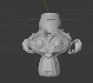
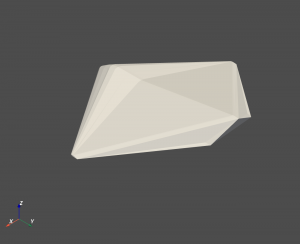
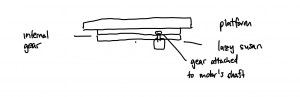
This week, on top of working in parallel with other team members to finalize our sensor, I was mainly responsible for the rotational mechanism and platform design. The individual work I did this week can be broken down into 3 main tasks. First is to design the overall design of the rotating platform. The platform would be mainly composed of the motor, a gear, a lazy susan bearing to reduce friction, a platform, a high-friction surface, an internal gear, and a support. The high-friction surface here is to simply help reduce the chance of the object slipping off-center while the platform is rotating. The support here is to give the platform itself enough height so that the motor can be put under. The motor with a gear attached to the shaft will be inside the platform. The lazy susan will be the base, and the internal gear will be attached on top of the lazy susan bearing, and the platform will be attached on the internal gear. The gear on the motor’s shaft will be connected to the internal gear, and when the motor rotates, the platform will rotate with it. Below is a rough diagram of the design. 

For the high-friction surface, I have done some research and reduced the materials down to Polyurethane foam, Isoprene rubber, Butadiene rubber, and Nitrile rubber which our team still has to analyze them together to see which one would fit our requirement best. 


After deciding on the rough design, I started choosing material that would work best for the platform itself. The platform will be a circular disc with a diameter of 35cm. I then did some rough estimation to compute the stress that the platform needs to be able to handle. From our maximum input object’s mass of 7kg, the maximum gravitational force that it can exert on the platform is around 68.67N. The lazy susan bearing our team might end up using has an inner diameter of around 19.5cm (or 0.0975 m radius). This would give us an area of around 0.03m2 that would not have any support. I simplified the stress analysis of this design down but it should still give a good estimation of the stress the object would apply, which is around 2300Nm. 


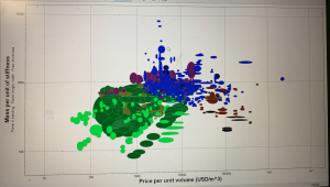
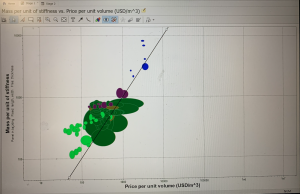
After that, I did more research on the material that would be able to handle this much stress, be cost-efficient and easily accessible, and easy to use (cut, coat, etc). I consulted with a friend in the Material Science program and we did some optimization based on cost and mass-to-stiffness ratio to narrow down the number of materials I had to do research on. Below is an image of the optimization graph. Note that we only looked into plastic and natural materials as they are easier to use and more easily accessible. The line in the second image is the optimization line. 


After that, I narrowed it down more to 3 materials: plywood, epoxy/hs carbon fiber, and balsa. The table belows shows the tradeoffs between different main properties that would affect our decision. Young’s modulus, specific stiffness, and yield strength are mainly to see if the material would be able to handle the amount of stress the object would exert on it or not. The price per unit volume is to keep this within our project’s contraint. The density is used to compute the mass of the platform (for computing the torque required and to stay within our Portability requirement).


Material Young’s Modulus (GPa) Specific Stiffness (MN.m/kg) Yield Strength (MPa) Density (kg/m3) Price per Unit Volume (USD/m3)
Plywood 3-4.5 3.98-6.06 8.1-9.9 700-800 385-488
Carbon Fiber 58-64 38.2-42.4 533-774 1490-1540 26200-31400
Balsa 0.23-0.28 0.817-1.09 0.8-1.5 240-300 1610-3230


From here, we can see that carbon fiber is the strongest but is very heavy and expensive and might not suit our project well. Balsa is very light but is not as strong (even if the values here are still higher than the stress I computed, it might be because of the simplified stress analysis I did). Thus, our group decides to use plywood which is strong, inexpensive, easy-to-cut, and not too heavy. With plywood, the maximum mass our of platform would just be around 0.6kg (computed using density and dimensions of the platform).


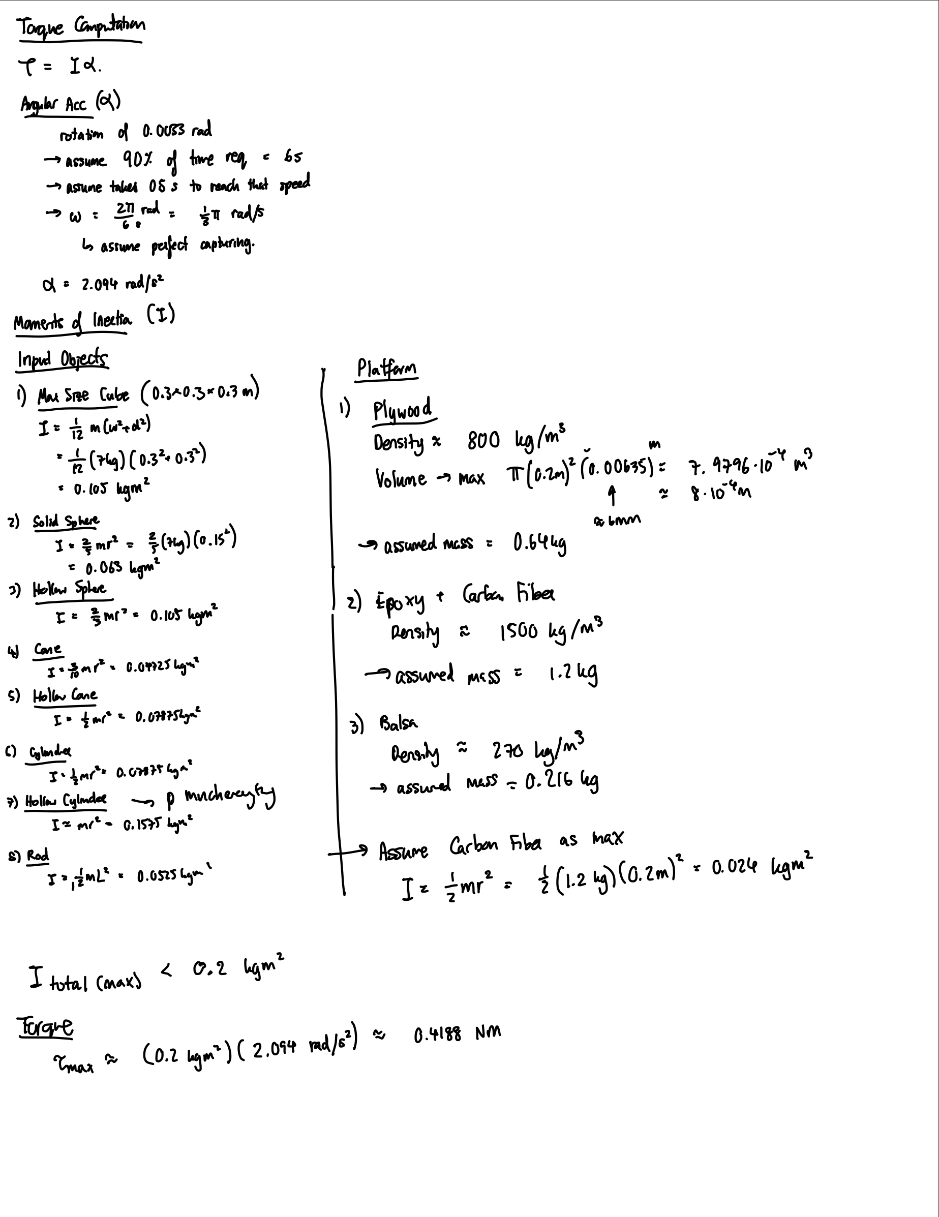
The final part of the main platform design is to choose the right motor for the project. The main 2 motors I looked into to rotate the platform are the servo motor and the stepper motor. A servo motor is a motor coupled with a feedback sensor to facilitate with positioning for precise velocity and acceleration. A stepper motor, on the other hand, is a motor that divides a full rotation into a number of equal steps. To figure out the motor used, I computed the torque required to rotate the platform with the maximum object size. From the density and dimensions of the platform, I computed that the plywood platform would weight around 0.64kg and carbon fiber would be around 1.2kg (I still accounted for the heaviest material and strongest material in case of a change in the future). From that I computed the moments of inertia which is around 0.024kgm2. For the input object, I used maximum size and different dimensions and shapes to cover most main and edge cases, the maximum moments of inertia computed is around 0.1575kgm2. Thus, the total maximum moments of inertia is less than 0.2kgm2. To get the torque, I also estimated the angular acceleration needed. From Alex’s computation, we need at least a rotation of 0.0033 rad per step to capture enough data to meet our accuracy requirement. Assuming that 10% of the time requirement, which is 6s, can be used for data capturing (so that we have more buffer for the algorithmic part since we don’t exactly know how complex it would actually be yet), we would get that the angular velocity is around /3rad/s. Assuming we want our motor to be able to reach that velocity fast enough (0.5s), we have an estimated acceleration of 2.094rad/s2. From here, the estimated torque needed to rotate the platform is around 0.4188Nm. Below is the rough computation made. 

Since we need a high torque and from our algorithm we would need an accurate step, the stepper motor is preferred. The two stepper motor I looked into are the NEMA 17 and NEMA 23. NEMA 17 has a holding torque of 0.45Nm, and NEMA 23 has a holding torque of 1.26Nm. Even though NEMA 17 seems like it might be enough, in my computation, I neglected the friction which would drastically affect the torque the motor has to supply. Moreover, I also neglected the energy that would be lost through using the internal gear to rotate the platform. Since NEMA 23 is not that much more expensive, I believed NEMA 23 would fit our project best. 

I’m currently still a little behind on schedule but I caught up a lot. Learning everything about stress, torque, and material took up most of my time for this week and computing different values and making sure the simplifications are not over-simplified were also a difficult task. I am a little behind in that I expected that I would have the gear and design fully drawn with dimensions written correctly. I would do that by putting in more work before the design reviews.


For next week, I hope to find all the specific parts for purchase and order them. I would also like to work on the design document. Once all the material and components arrive, I would start assembling the platform.