This week, on top of working in parallel with other team members to finalize our sensor, I was mainly responsible for the rotational mechanism and platform design. The individual work I did this week can be broken down into 3 main tasks. First is to design the overall design of the rotating platform. The platform would be mainly composed of the motor, a gear, a lazy susan bearing to reduce friction, a platform, a high-friction surface, an internal gear, and a support. The high-friction surface here is to simply help reduce the chance of the object slipping off-center while the platform is rotating. The support here is to give the platform itself enough height so that the motor can be put under. The motor with a gear attached to the shaft will be inside the platform. The lazy susan will be the base, and the internal gear will be attached on top of the lazy susan bearing, and the platform will be attached on the internal gear. The gear on the motor’s shaft will be connected to the internal gear, and when the motor rotates, the platform will rotate with it. Below is a rough diagram of the design.

For the high-friction surface, I have done some research and reduced the materials down to Polyurethane foam, Isoprene rubber, Butadiene rubber, and Nitrile rubber which our team still has to analyze them together to see which one would fit our requirement best.
After deciding on the rough design, I started choosing material that would work best for the platform itself. The platform will be a circular disc with a diameter of 35cm. I then did some rough estimation to compute the stress that the platform needs to be able to handle. From our maximum input object’s mass of 7kg, the maximum gravitational force that it can exert on the platform is around 68.67N. The lazy susan bearing our team might end up using has an inner diameter of around 19.5cm (or 0.0975 m radius). This would give us an area of around 0.03m2 that would not have any support. I simplified the stress analysis of this design down but it should still give a good estimation of the stress the object would apply, which is around 2300Nm.
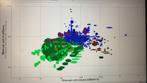
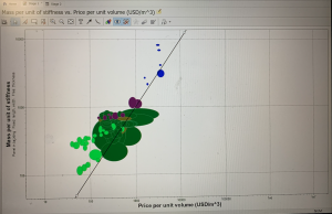
After that, I did more research on the material that would be able to handle this much stress, be cost-efficient and easily accessible, and easy to use (cut, coat, etc). I consulted with a friend in the Material Science program and we did some optimization based on cost and mass-to-stiffness ratio to narrow down the number of materials I had to do research on. Below is an image of the optimization graph. Note that we only looked into plastic and natural materials as they are easier to use and more easily accessible. The line in the second image is the optimization line.


After that, I narrowed it down more to 3 materials: plywood, epoxy/hs carbon fiber, and balsa. The table belows shows the tradeoffs between different main properties that would affect our decision. Young’s modulus, specific stiffness, and yield strength are mainly to see if the material would be able to handle the amount of stress the object would exert on it or not. The price per unit volume is to keep this within our project’s contraint. The density is used to compute the mass of the platform (for computing the torque required and to stay within our Portability requirement).
| Material | Young’s Modulus (GPa) | Specific Stiffness (MN.m/kg) | Yield Strength (MPa) | Density (kg/m3) | Price per Unit Volume (USD/m3) |
| Plywood | 3-4.5 | 3.98-6.06 | 8.1-9.9 | 700-800 | 385-488 |
| Carbon Fiber | 58-64 | 38.2-42.4 | 533-774 | 1490-1540 | 26200-31400 |
| Balsa | 0.23-0.28 | 0.817-1.09 | 0.8-1.5 | 240-300 | 1610-3230 |
From here, we can see that carbon fiber is the strongest but is very heavy and expensive and might not suit our project well. Balsa is very light but is not as strong (even if the values here are still higher than the stress I computed, it might be because of the simplified stress analysis I did). Thus, our group decides to use plywood which is strong, inexpensive, easy-to-cut, and not too heavy. With plywood, the maximum mass our of platform would just be around 0.6kg (computed using density and dimensions of the platform).
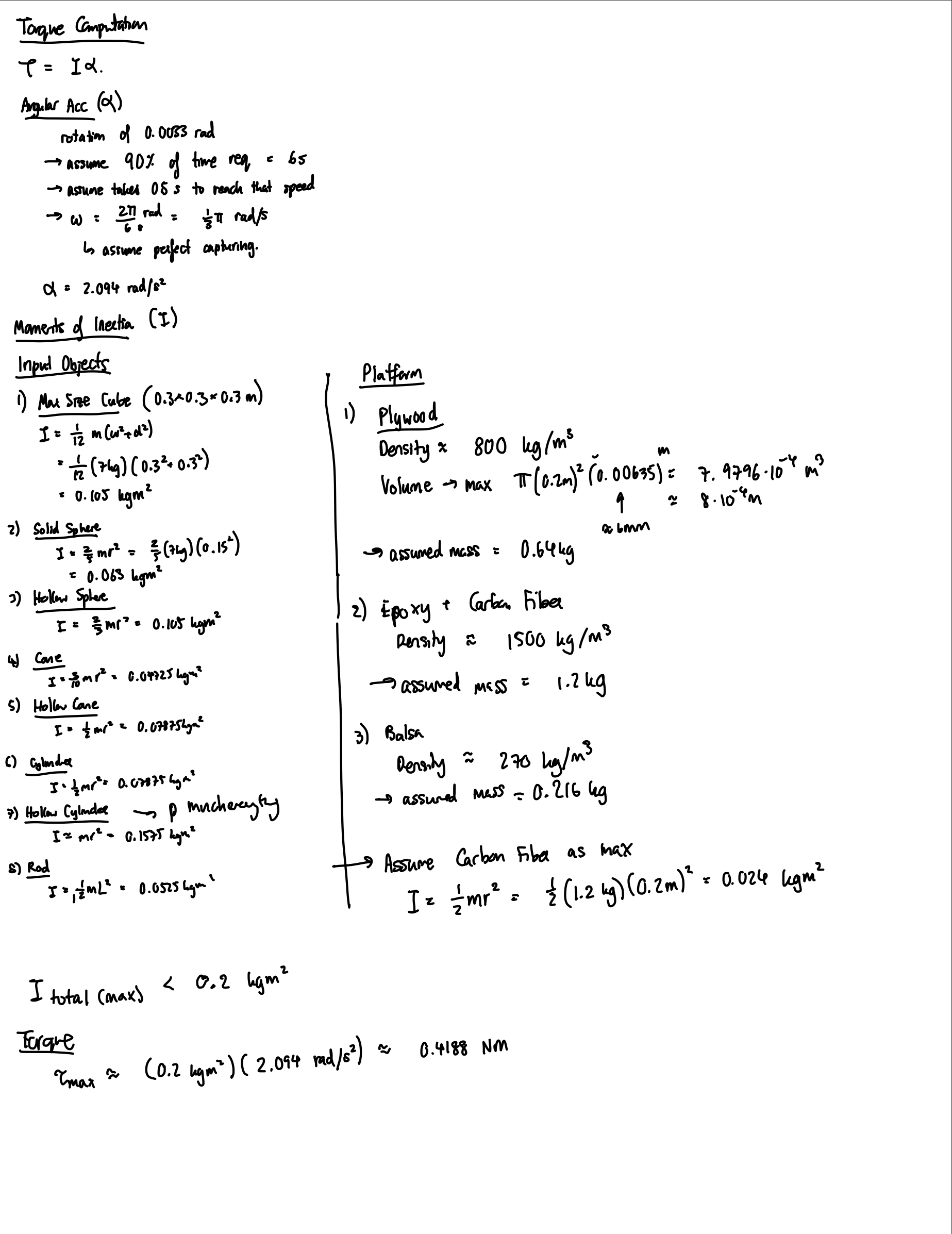
The final part of the main platform design is to choose the right motor for the project. The main 2 motors I looked into to rotate the platform are the servo motor and the stepper motor. A servo motor is a motor coupled with a feedback sensor to facilitate with positioning for precise velocity and acceleration. A stepper motor, on the other hand, is a motor that divides a full rotation into a number of equal steps. To figure out the motor used, I computed the torque required to rotate the platform with the maximum object size. From the density and dimensions of the platform, I computed that the plywood platform would weight around 0.64kg and carbon fiber would be around 1.2kg (I still accounted for the heaviest material and strongest material in case of a change in the future). From that I computed the moments of inertia which is around 0.024kgm2. For the input object, I used maximum size and different dimensions and shapes to cover most main and edge cases, the maximum moments of inertia computed is around 0.1575kgm2. Thus, the total maximum moments of inertia is less than 0.2kgm2. To get the torque, I also estimated the angular acceleration needed. From Alex’s computation, we need at least a rotation of 0.0033 rad per step to capture enough data to meet our accuracy requirement. Assuming that 10% of the time requirement, which is 6s, can be used for data capturing (so that we have more buffer for the algorithmic part since we don’t exactly know how complex it would actually be yet), we would get that the angular velocity is around /3rad/s. Assuming we want our motor to be able to reach that velocity fast enough (0.5s), we have an estimated acceleration of 2.094rad/s2. From here, the estimated torque needed to rotate the platform is around 0.4188Nm. Below is the rough computation made.

Since we need a high torque and from our algorithm we would need an accurate step, the stepper motor is preferred. The two stepper motor I looked into are the NEMA 17 and NEMA 23. NEMA 17 has a holding torque of 0.45Nm, and NEMA 23 has a holding torque of 1.26Nm. Even though NEMA 17 seems like it might be enough, in my computation, I neglected the friction which would drastically affect the torque the motor has to supply. Moreover, I also neglected the energy that would be lost through using the internal gear to rotate the platform. Since NEMA 23 is not that much more expensive, I believed NEMA 23 would fit our project best.
I’m currently still a little behind on schedule but I caught up a lot. Learning everything about stress, torque, and material took up most of my time for this week and computing different values and making sure the simplifications are not over-simplified were also a difficult task. I am a little behind in that I expected that I would have the gear and design fully drawn with dimensions written correctly. I would do that by putting in more work before the design reviews.
For next week, I hope to find all the specific parts for purchase and order them. I would also like to work on the design document. Once all the material and components arrive, I would start assembling the platform.