Aaron’s Status Report for 10/17/26

For the week of October 4th–11th, I focused on moving our ITERATION 1 design from completed CAD files into 3D printed parts to assemble. We finished printing all of the designed components for the arm and began assembling the base. Reaching this stage was an important milestone because it allowed us to start checking how the printed pieces fit together outside of the SolidWorks assembly.

Alongside the printing process, I started refining our CAD models for a few purchased components now that we have received the physical measurements, including the motors, bearings, and power system. I updated these models to match the parts we plan to use as closely as possible so that the mounting locations, clearances, shaft dimensions, and enclosure measurements remain accurate during assembly, as we realized the motor enclosure for one of the bases was too tight. This helped reduce the risk that differences between placeholder models and the real components would require larger redesigns later.

All of the modeling and printing work planned for Iteration 1 is now complete with revisions still to be printed. However, the physical assembly is slightly behind our original schedule: we’ve started with the base, but still need to complete the rest of the arm and are waiting for several additional parts to arrive. Once those parts are available, I will need to verify the fit of the motors and bearings, complete the joint assemblies, and correct or reprint any components that do not match the purchased hardware.

I am on schedule with the CAD and printing portions of my Iteration 1 responsibilities, but we will need to make up some time during assembly. The completed model and printed parts give us a solid foundation, and the remaining work is primarily integration and fit verification.

For next week, I plan to:

  • Continue assembling the base and remaining arm sections.
  • Install the motors, bearings, and power components as the remaining hardware arrives.
  • Measure the purchased components and compare them against the refined CAD models.
  • Test joint alignment, clearances, and range of motion during assembly.
  • Update or reprint any parts that require dimensional corrections.
  • Document the completed Iteration 1 assembly and any design changes needed for the next iteration.

Jonathan’s Status Report for 10/17/26

For this week, I dedicated my time toward structuring our ROS2 repository on the Jetson Nano, developing custom kinematic and torque analysis scripts in Python, and helping finalize our hardware parts list for Iteration 1. A major milestone for this week was creating a comprehensive mathematical simulation model of our 6DOF arm to verify that our selected serial bus servos can handle expected joint loads across our workspace (see below).

On the software and simulation side, I expanded our ROS2 environment on the Jetson Nano by installing necessary development utilities, creating our team’s official GitHub repository, and laying out the core software framework for our project. To validate our mechanical design before 3D printing, I wrote a dedicated Python robot class to process our arm’s link lengths, joint limits, and component masses. Using this class, I implemented forward kinematics, Jacobian matrix calculations, and inverse kinematics solvers, sampling various coordinate points across our 3D workspace. By coupling these kinematic transformations with static load physics equations, I confirmed that our calculated joint torques fall comfortably within the operating limits of our smart serial bus servos for Iteration 1 (see below for graph of workspace points tested).

Beyond simulation, I collaborated with the team to finalize our master hardware parts list for Iteration 1 so we can get all necessary servos, bearings, and power components ordered. We also wrapped up the remaining CAD design details for Iteration 1. While finalizing the CAD model took longer than anticipated and pushed the start of 3D printing to this weekend, we now have a solid design ready to manufacture.

I am mostly on track with my individual software and analysis tasks, though as a team we are slightly behind schedule on physical assembly for Iteration 1, so we will need to pick up the pace once parts finish printing and hardware arrives.

For next week, I plan to:

  • Clean up and document the Python torque and workspace calculation scripts.
  • Expand our ROS2 software framework and construct a preliminary URDF model to visualize the robot arm in RViz2.
  • Begin setting up the initial tf2 frame tree structure for coordinate transformations between the robot base and end-effector.
  • Collaborate with Bryan on 3D printing execution and begin physical assembly of Iteration 1 as motor hardware arrives.

Team Status Report for 10/3/2026

For the week of September 27th – October 3rd, our team made significant progress toward finalizing the Iteration 1 design of our 6-DOF robotic arm. Our main focus was completing the mechanical design, validating the robot through simulation and torque analysis, finalizing the hardware parts list, and preparing for physical implementation when our ordered parts begin arriving.

A major area of progress was remodeling our robot around the dimensions and geometry of the UR3e model from last week. We used the UR3e’s dimensions as a reference for our own kinematic model, allowing us to use a proven robot configuration while adapting the design to our 3D-printed links and selected smart bus servos. The updated SolidWorks assembly now contains modeled representations of the purchased smart bus serial servos, power supply, shafts, and other components. The end effector was also modified to support a pen for our intended testing.

We also performed several simulations to validate the updated design. FEA stress testing was used to identify and strengthen weak areas of the printed components, while MuJoCo was used to visualize the robot and verify its motion and geometry with the SolidWorks assembly. Simultaneously, Python kinematic and torque analysis tools were used to evaluate loads at every robot joint and confirm that the purchased servos can support the weight of the robot arm. The results of these showed that the shoulder and elbow joints are near the practical limits of our selected servos at the full UR3e dimensions. To address this, the current design uses two servos at each of these joints, along with a reduction mechanism and counterbalance spring to reduce the load and side forces on the servos.

On the software side, we continued developing our ROS2 environment on the Jetson and established the project’s GitHub repository and initial software structure. We also determined that OpenCV AprilTag detection is a better fit for our vision system than using a YOLO26 model, since AprilTags can be detected directly (using the apriltags OpenCV library) without training an object detection model. This should provide a simpler and more efficient solution for our Jetson Orin Nano and Intel RealSense D455 camera setup.

Finally, we worked together to finalize the Iteration 1 master parts list and identify remaining hardware such as bearings, screws, shafts, tubing, and additional filament. With the mechanical design and simulations largely complete, our primary risk is now transitioning successfully into fabrication and assembly. The first print runs are expected to require approximately 35 hours and 900 g of filament, so we will need to carefully prioritize the initial parts and quickly iterate on any components that require redesign.

Our project is slightly behind the original schedule since the CAD design and subsequent validation took more time than anticipated. Therefore, we have had to push back most of our schedule by about a week, so printing and assembly will commence this following week.

For next week, our team plans to:

  • Begin printing the finalized Iteration 1 components, starting with the base.
  • Measure and test initial prints before committing to the full build.
  • Order any remaining hardware and additional filament required for assembly.
  • Begin assembling the printed components and servos as parts become available.
  • Continue developing the ROS2 framework, including the URDF and tf2 structure.
  • Begin prototyping AprilTag tracking using the Jetson and RealSense camera.

Bryan’s Status Report for 10/3/2026

For the week of September 27th – October 3rd, I focused on helping finalize the Iteration 1 system design and narrowing down the CV approach for our 6-DOF robot arm. In addition, I helped finalize the master parts list, including the required components, quantities, and pricing. With our overall Iteration 1 design done, we are now in a better position to move forward with more implementation-related work.

One of my main areas of research was determining the best approach for AprilTag detection. After looking over documentation and comparing OpenCV-based AprilTag detection with using a YOLO26 model, I determined that OpenCV is the better choice for our application. Since OpenCV already has a library dedicated to detecting AprilTags, a YOLOv26 model trained on these tags would be less appropriate. OpenCV should also provide a simpler and less computation-heavy on the NVIDIA Jetson Orin Nano while integrating well with the Intel RealSense D455. This approach will allow us to focus the vision system on reliable AprilTag detection and tracking without adding unnecessary model-training time.

I also continued working with the team on the overall Iteration 1 design and component selection. With the parts list now largely finalized, we have a clearer picture of the electrical and mechanical components required for the system. This will help us move toward integrating the camera, computing hardware, servo motors, and other components into the final design.

For next week, I aim to:

  • Prototype OpenCV AprilTag detection and tracking on the NVIDIA Jetson and Intel RealSense D455.
  • Start configuring motors and power supply once they come in.
  • Continue refining the Iteration 1 design and preparing components for system integration.

Aaron’s Status Report for 10/3

For the week of Sep 27th – Oct 3rd, I focused on remodeling our robot to the dimensions of the UR3e robot from last week’s decision. Jonathan and I looked at the UR3e resources online and discovered a spreadsheet containing the transformation matrices for the robot’s positioning and movement of each joint. We wanted to take the dimensions from something that has proved to work and apply our own torque calculations adjusted to our motors and 3d printed links and joint housing.

First, I checked the specifications of our purchased components for the Hiwonder and Feetech smart servos to see if they had compatible communication protocols, which would allow one controller to operate all twelve servos on the same bus.
UR3e Denavit-Hartenberg parameters and coordinate transformations

Above is the UR3e parameters and coordinate transformations that we adopted; the spreadsheet contained variable inputs and visualizations of joint positions on the right, so we could experiment with different positionings. Universal Robotics’ website also contained the downloadable CAD models.

Initial UR3e-based robot rendering with the exterior casing removed

In SolidWorks, I was able to adapt the model’s end effector to hold a pen, then deconstruct the outer casing (since they would require too much filament to print) to preserve the UR3e’s dimensions 1:1.

I then checked whether the servos we got could actually drive the arm with 1:1 dimensions, where I discovered that the shoulder and elbow are close to the servos’ practical limits. To prevent those joints from overheating, I designed for two servos at both the shoulder and elbow, which creates a 3:1 reduction in force and a counterbalance spring based on several joint designs online. My hypothesis is that this reduces unnecessary side loads on the servo shafts and should keep the arm stable since we don’t want it to wobble too much.

I built the updated assembly in SolidWorks with some AI assistance using a scripted workflow; our model now contains 46 printable parts as well as AI-assisted CAD reconstructions of our purchased servos and PSU, as well as some shafts, screws, and tubes that we will likely need to purchase as well to replace sections in which 3D printed parts would bear too much load.

For testing, I tested the assembly by:

  1. I performed von Mises stress testing through finite-element analysis (FEA) and redesigned weak parts with thicker transitions and rounded bottoms  (fillet bottoms) which I’ve seen in the past help with structural integrity
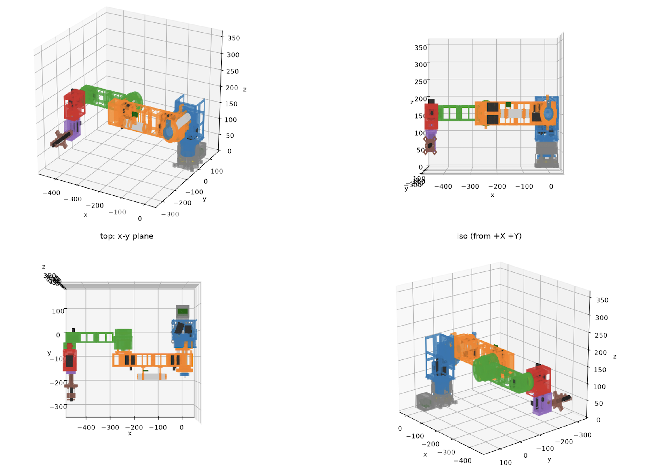
  2. I used MuJoCo simulations to assemble and visualize the finalized robot, check its motion, and compare the simulated geometry with the SolidWorks assembly

MuJoCo robot simulation from four viewpoints

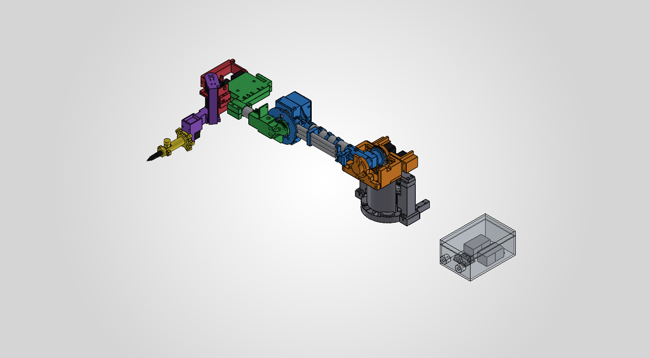
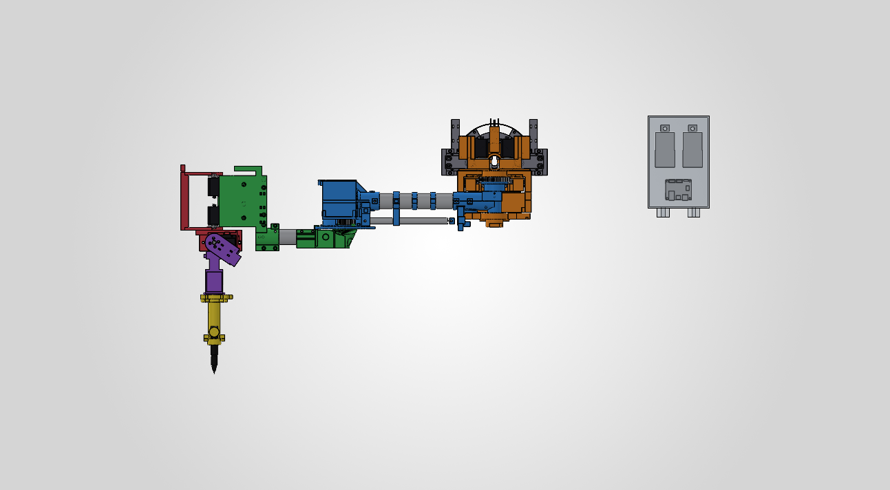
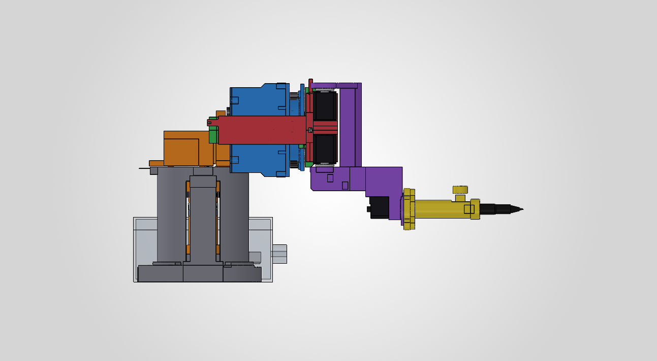
Our final representation in SolidWorks looks like this, with the gray parts being purchased rods and everything else 3D printed links and a manually adjusted end effector for Iteration 1:

Isometric view of the deconstructed robot arm CAD assembly

Top view of the deconstructed robot arm CAD assembly

Side view of the wrist and pen end effector

We have started printing the first plate tonight, and it would likely need around 40 hours of printing, approximately ~900g of filament, which is very close to the 1kg we purchased, so we may need to account for a few more rolls.

Overall the CAD design and simulation work is essentially complete and on schedule, but the biggest risk is with printing and iterating on the prints, as well as ordering the additional parts needed for assembly.

For next week, I plan to:

  1. Print and measure the base and print the base plates first before printing any fully sized arm parts
  2. Outline the remaining order form for additional tubes, screws, filament, and bearings we may need to purchase
  3. Begin printing the finalized build plates in order from bottom to top (with exception of the end effector which we should test early)
  4. Start assembling the printed components and iterate on redesigns quickly

Jonathan’s Status Report for 10/3/26

For this third week, I dedicated my time toward structuring our ROS2 repository on the Jetson Nano, developing custom kinematic and torque analysis scripts in Python, and helping finalize our hardware parts list for Iteration 1. A major milestone for this week was creating a comprehensive mathematical model of our 6DOF arm to verify that our selected serial bus servos can handle expected joint loads across our workspace (see below).

On the software and simulation side, I expanded our ROS2 environment on the Jetson Nano by installing necessary development utilities, creating our team’s official GitHub repository, and laying out the core software framework for our project. To validate our mechanical design before 3D printing, I wrote a dedicated Python robot class to process our arm’s link lengths, joint limits, and component masses. Using this class, I implemented forward kinematics, Jacobian matrix calculations, and inverse kinematics solvers, sampling various coordinate points across our 3D workspace. By coupling these kinematic transformations with static load physics equations, I confirmed that our calculated joint torques fall comfortably within the operating limits of our smart serial bus servos for Iteration 1 (see below for workspace points tested).

Outside of that, I collaborated with the team to finalize our master hardware parts list for Iteration 1 so we can get all necessary servos and power components ordered. Aaron is still working on the the remaining CAD design details for Iteration 1, but I have been giving feedback along the way. Finalizing the CAD model took longer than anticipated, and this pushed the start of 3D printing to this weekend which is a bit later than expected based on our schedule.

I am mostly on track with my individual software and analysis tasks, though as a team we are slightly behind schedule on physical assembly for Iteration 1, so we will need to pick up the pace for printing and using the hardware.

For next week, I plan to:

  • Clean up and document the Python torque and workspace calculation scripts.
  • Expand our ROS2 software framework and construct a preliminary URDF model to visualize the robot arm in RViz2.
  • Begin setting up the initial tf2 frame tree structure for coordinate transformations between the robot base and end-effector.
  • Collaborate with Bryan on 3D printing execution and begin physical assembly of Iteration 1 as motor hardware arrives.

Team Status Report for 9/26/26

Team Status Report

For the week of September 20th–26th, we worked on bringing up the embedded software platform, grounding the mechanical design in a reputable six-axis reference model, refining the Iteration 1 parts list, and preparing the CAD and presentation materials needed for the next stage of the project.

Project Risks & Management Strategies

The biggest risk was figuring out the structural requirements of our manually inferred dimensions on our previous CAD model, as we didn’t have a good basis to figure out if the links would sustain the weight of the joints.

We are managing this risk by comparing our measurements now against Universal Robots’ UR3e, and we aim to calculate the joint torques using the selected components’ estimated masses, and prepare some comprehensive SolidWorks motion and load simulations before printing the final links for this iteration.

Another risk we’ve identified is the integration between the CAD model, ROS2 coordinates, computer vision, and the physical arm. We are attempting to reduce that risk through developing the Jetson software environment early; this week, we’ve already set it up and ran it, and we’re collaborating on defining the CAD workspace and joint constraints before we print the pieces.

System Design Changes

We chose to use the UR3e as reference for dimensions and kinematics, instead of deriving all link lengths and joint placements from scratch which would require continuous testing, and this mechanical specs can get a bit complicated when isn’t the primary expertise or focus of our group. We imported the UR3e STEP model into SolidWorks and recorded its links, joint placement, proportions, and reachable workspace.

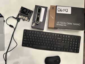
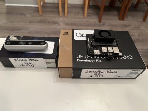
We also set up and installed the OS on our NVIDIA Jetson Orin Nano with JetPack 7 Ubuntu and ROS2. This would give us a physical development platform for testing ROS2 nodes and preparing the coordinate-frame and motion-planning architecture before we assemble the complete arm, so we could allow time extra time for adapting the reference links and joints and configuring the Jetson.

Project Schedule Status

The project remains mostly on schedule. The Jetson environment, initial ROS2 publisher/subscriber test, UR3e reference-model import, early test printing, and preliminary CAD work were completed this week. The Iteration 1 CAD, joint-limit definition, surface modeling, and torque/workspace analysis are scheduled through October 3rd and remain in progress. The parts list and the remaining calculations need to be finalized promptly so that the team can place the hardware order and begin manufacturing without consuming the integration buffer later in the semester.

Team Progress & Highlights

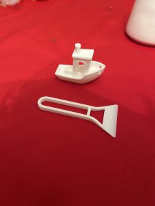
The team successfully configured the Jetson Orin Nano from scratch, installed JetPack 7 Ubuntu and ROS2, and verified the environment with ROS2 publisher and subscriber nodes running simultaneously. We also established an initial 3D-printing environment and completed some basic test prints to estimate manufacturing time and evaluate print settings.
Week-Specific Considerations

Part A: Public Health, Safety, and Welfare
Written by Bryan Hong

When it comes to public health, safety, and welfare, our project may not appear at first glance to directly impact any of the three. However, by placing the means of production into the hands of the artist, we have helped the latter avoid employing the services of a third-party manufacturing company that may rely on unethical labor practices and/or unsafe working conditions. By enabling artists and creators to reproduce their work in-house, our system reduces the reliance on these morally-questionable third party manufacturers, and thus indirectly improves global health, safety, and welfare, ensuring that the physical manifestation of art does not come at the cost of others’ health.

Part B: Social Factors
Written by Aaron Tang

Our robot arm is intended to be used primarily by digital artists, students, and researchers who want to transform a digital line drawing into a physical drawing on curved surfaces.

In order to make this design accessible for social and educational settings, our 1. web interface shouldn’t require experience with robotics, CAD, or any sort of electrical/software engineering. Users should be able to submit a drawing on our interface, select a marker color, and follow the robot’s status and receive clear feedback.

This would make the system valuable for classroom demonstrations and creative environments where artists who don’t have engineering backgrounds can safely and easily reproduce their art. It would also take into consideration people who have difficulty drawing manually on large, elevated, or unusually positioned surfaces.

We have also considered some concerns that robotic drawing tools could replace human creativity. Our goal is to create a tool to assist artists, not replace them: the user should ultimately still be responsible for their own artwork and creative decisions, while the robot simply transfers that work exactly stroke by stroke to a physical surface. The system should also respect ownership and consent by reproducing only artwork that artists consent to, and keeping submitted drawings under the user’s control.

Part C: Economic Factors
Written by Jonathan Waller

Our 6DOF drawing robot addresses economic factors in production and consumption by providing a low-cost, accessible alternative to expensive industrial machinery. By utilizing standard off-the-shelf smart servos, 3D-printed structural components, and open-source software, our design significantly reduces the bill of materials. This allows the 6DOF arm to be affordable relative to its capabilities. The system was designed with independent creators and digital artists in mind, allowing them to produce small batches of custom physical works directly from their digital art. Instead of relying on costly third-party manufacturing services or full-scale assembly lines, artists can preserve their preferred digital workflow, fine-tune their designs locally, and economically handle low-volume production without a heavy financial investment.

Bryan’s Status Report for 9/26/2026

For the week of September 20th – 26th,  I focused on continuing my research and development into Iteration 1 of our 6-DOF robot arm. After initially choosing a YOLO model for AprilTag (used for calibration) detection, my team and I discussed using the NVIDIA Isaac ROS or OpenCV instead, since it is more optimized for AprilTag detection. However, since our design has not yet been fully finalized, much of our final electrical components have not been finalized yet as we do not have accurate enough data for torque calculations. In addition, we are still investigating whether a dedicated microcontroller will be necessary for our final system.

One of my main areas of research this week was determining how AprilTag tracking could be incorporated into our system. I investigated using OpenCV-based and Isaac ROS AprilTag detection approaches as alternatives to using a YOLO-based object-detection pipeline. OpenCV would potentially provide a simpler solution for identifying AprilTags, since the architecture is quite easy to use, which cannot be as easily said about Isaac ROS. This could simplify the computer-vision pipeline compared to training a YOLO model specifically for AprilTag detection. However, I am still evaluating the tradeoffs between the approaches, specifically in terms of detection accuracy, implementation ability, and how well each method would integrate with the NVIDIA Jetson Orin Nano and Intel RealSense Depth Camera D455.

I also continued investigating the smart bus serial servo motors that we discussed last week. While Hiwonder, Feetech, and Waveshare are still candidates, I was unable to definitively select the motors because our team has not yet finalized the Iteration 1 design, and as a result, we do not have an accurate estimation for the required torque at each joint. Therefore, we decided to hold off for the time being to confirm our final Iteration 1 design, since prematurely ordering motors that are too weak to support the joints is a real concern. In the meantime, I will continue searching more approved vendors such as DigiKey to source smart bus serial motors from.

Overall, this week was primarily focused on narrowing down the computer-vision and embedded-system architecture while continuing to work with my team on the overall design. Since our Iteration 1 design is still a work in progress, my work has consisted more heavily of research and comparison instead of final component selection. Once the mechanical design is finalized, I will be able to use the resulting simulation data to make appropriate decisions about the servo motors, power requirements, and camera placement.

For next week, I aim to complete the following:

  • Continue comparing OpenCV AprilTag detection against YOLO-based detection and determine which approach is better suited for our system
  • Test or prototype AprilTag tracking using the NVIDIA Jetson and camera setup.
  • Collaborate with the team to finalize the Iteration 1 mechanical and electrical design.
  • Use updated simulation data to determine the torque requirements for each smart bus serial servo.
  • Narrow down and finalize the specific smart bus serial servo motors for each joint.
  • Assist the team with refining the master parts list, including component prices, links, specifications, and quantities.

Jonathan’s Status Report for 9/26/26

For this second week, I dedicated my time toward bringing up our robot’s software and hardware stacks, establishing our 3D printing workflow, assisting with mechanical calculations, and preparing for our upcoming design presentation. A major milestone for this week was receiving our embedded computing platform and setting up a functional, local ROS2 development environment directly on the physical hardware (see below).

I spent significant time getting the NVIDIA Jetson Orin Nano up and running from scratch. Because the board arrived without an operating system or peripherals, I sourced a DisplayPort cable and a high-speed microSD card for storage, then flashed the Jetson with JetPack 7 Ubuntu. Once the OS was configured, I installed essential command-line tools like tmux and vim alongside ROS2, verifying system stability and environment setups by running the first ROS2 test with 2 publisher and subscriber nodes running simultaneously on the device. Additionally, I helped establish our team’s 3D printing workflow by slicing and executing test prints to evaluate how much time each print will take (photos of these test prints will be on this week’s team report).

Beyond individual setup tasks, I collaborated with the team on refining our master hardware parts list so we can finalize and submit our order for Iteration 1. I also worked alongside the team on CAD Iteration 1, initiating torque and workspace calculations to inform joint placements, limb lengths, and motor specs. Finally, I drafted content for our upcoming design presentation and spent time practicing, as I will be serving as the team’s primary presenter.

I am mostly on track relative to our project roadmap, though we need to make sure the parts list is finalized soon and finish our calculations on torque and workspace in the next few days.

For next week, I plan to:

  • Finalize and submit our master hardware parts list for Iteration 1 components.
  • Deliver our team’s design presentation and analyze the feedback from faculty and TAs.
  • Begin setting up the general software project layout (ROS2) and outline the initial tf2 frame tree structure.
  • Finish torque and workspace calculations with the team to finalize motor placements and limb dimensions in CAD.

Aaron’s Status Report for 9/26

For the week of September 20th-26th, I continued our Iteration 1 CAD design of our 6DoF robotic arm in SolidWorks. After some discussion with the team, we decided to base our structural requirements on an already established and tested design instead of choosing every dimension from scratch.

We selected the Universal Robots UR3e (which is widely used in different industries), since it was essentially the lightest and smallest model from their catalog. It fulfilled all our design specifications as it contained 6 joints and thus 6 axes of rotation and some safety functions we could take inspiration from.

I used it as our reference and imported its STEP model into SolidWorks, which I used to note down its link lengths, joint placement, proportions, reachable workspace, and then used those measurements as a starting point for our arm. The design will not be an exact copy of the UR3e because it needs to fit to our selected actuators, 3D-printed parts, PSU, and end effector (pen gripper)– however, the reference model would give us a more dependable baseline since they’re already validated dimensions.

This week, I recorded some of the UR3e geometry, specifically its physical limits in CAD and how many degrees of freedom it had for six joints. For our robot, the joint limits need to not collide with themselves or block anything and still let the end effector to reach the object inside of our 0.4m x 0.4m x 0.4m workspace. This work is still in progress since the limits depend on the dimensions of our selected servos and the mechanical design of the 3D printed links.

My Iteration 1 CAD along with the joint simulations and surface modeling (which I’ve modeled as a simple cylindrical surface already), and physics work is scheduled through October 3rd, so I’m currently in progress and on track. What’s still remaining is finalizing joint limits by also finalizing what hardware we’re purchasing, build out the Iteration 1 CAD and run it in the workspace with torque simulations/calculations.

For next week, I plan to:

1. Finalize our hardware parts with their physical limits and calculate the range of motion for all six joints
2. Run a SolidWorks Motion simulation to record the arm’s reachable workspace, I need to figure out how to exactly simulate the physics to see if the weight of the arm is also low enough to sustain the end effector without falling over
3. Determine whether our arm’s shoulder needs a stronger actuator, or some sort of counterbalance (I was thinking of accommodating the design for a vise to hold it down)
4. Update the Iteration 1 SolidWorks assembly based on the simulation results and prepare the CAD files for printing