Aaron’s Status Report for 10/17/26

For the week of October 4th–11th, I focused on moving our ITERATION 1 design from completed CAD files into 3D printed parts to assemble. We finished printing all of the designed components for the arm and began assembling the base. Reaching this stage was an important milestone because it allowed us to start checking how the printed pieces fit together outside of the SolidWorks assembly.

Alongside the printing process, I started refining our CAD models for a few purchased components now that we have received the physical measurements, including the motors, bearings, and power system. I updated these models to match the parts we plan to use as closely as possible so that the mounting locations, clearances, shaft dimensions, and enclosure measurements remain accurate during assembly, as we realized the motor enclosure for one of the bases was too tight. This helped reduce the risk that differences between placeholder models and the real components would require larger redesigns later.

All of the modeling and printing work planned for Iteration 1 is now complete with revisions still to be printed. However, the physical assembly is slightly behind our original schedule: we’ve started with the base, but still need to complete the rest of the arm and are waiting for several additional parts to arrive. Once those parts are available, I will need to verify the fit of the motors and bearings, complete the joint assemblies, and correct or reprint any components that do not match the purchased hardware.

I am on schedule with the CAD and printing portions of my Iteration 1 responsibilities, but we will need to make up some time during assembly. The completed model and printed parts give us a solid foundation, and the remaining work is primarily integration and fit verification.

For next week, I plan to:

  • Continue assembling the base and remaining arm sections.
  • Install the motors, bearings, and power components as the remaining hardware arrives.
  • Measure the purchased components and compare them against the refined CAD models.
  • Test joint alignment, clearances, and range of motion during assembly.
  • Update or reprint any parts that require dimensional corrections.
  • Document the completed Iteration 1 assembly and any design changes needed for the next iteration.

Aaron’s Status Report for 10/3

For the week of Sep 27th – Oct 3rd, I focused on remodeling our robot to the dimensions of the UR3e robot from last week’s decision. Jonathan and I looked at the UR3e resources online and discovered a spreadsheet containing the transformation matrices for the robot’s positioning and movement of each joint. We wanted to take the dimensions from something that has proved to work and apply our own torque calculations adjusted to our motors and 3d printed links and joint housing.

First, I checked the specifications of our purchased components for the Hiwonder and Feetech smart servos to see if they had compatible communication protocols, which would allow one controller to operate all twelve servos on the same bus.
UR3e Denavit-Hartenberg parameters and coordinate transformations

Above is the UR3e parameters and coordinate transformations that we adopted; the spreadsheet contained variable inputs and visualizations of joint positions on the right, so we could experiment with different positionings. Universal Robotics’ website also contained the downloadable CAD models.

Initial UR3e-based robot rendering with the exterior casing removed

In SolidWorks, I was able to adapt the model’s end effector to hold a pen, then deconstruct the outer casing (since they would require too much filament to print) to preserve the UR3e’s dimensions 1:1.

I then checked whether the servos we got could actually drive the arm with 1:1 dimensions, where I discovered that the shoulder and elbow are close to the servos’ practical limits. To prevent those joints from overheating, I designed for two servos at both the shoulder and elbow, which creates a 3:1 reduction in force and a counterbalance spring based on several joint designs online. My hypothesis is that this reduces unnecessary side loads on the servo shafts and should keep the arm stable since we don’t want it to wobble too much.

I built the updated assembly in SolidWorks with some AI assistance using a scripted workflow; our model now contains 46 printable parts as well as AI-assisted CAD reconstructions of our purchased servos and PSU, as well as some shafts, screws, and tubes that we will likely need to purchase as well to replace sections in which 3D printed parts would bear too much load.

For testing, I tested the assembly by:

  1. I performed von Mises stress testing through finite-element analysis (FEA) and redesigned weak parts with thicker transitions and rounded bottoms  (fillet bottoms) which I’ve seen in the past help with structural integrity
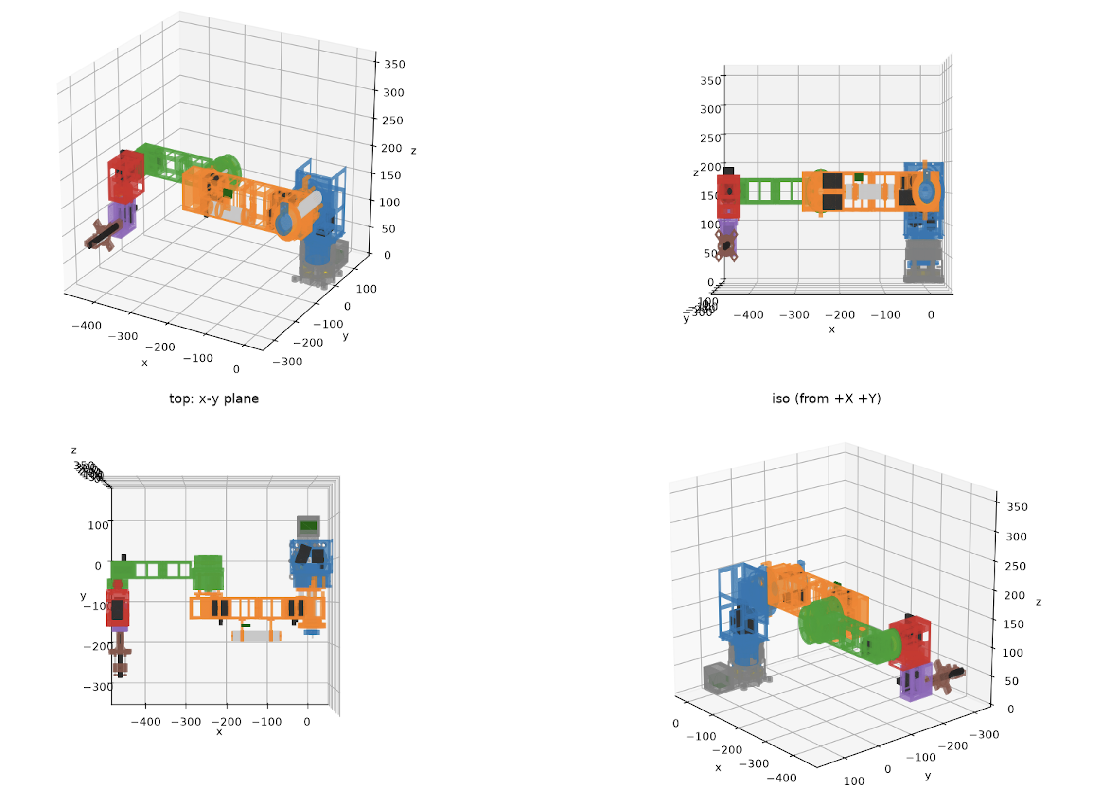
  2. I used MuJoCo simulations to assemble and visualize the finalized robot, check its motion, and compare the simulated geometry with the SolidWorks assembly

MuJoCo robot simulation from four viewpoints

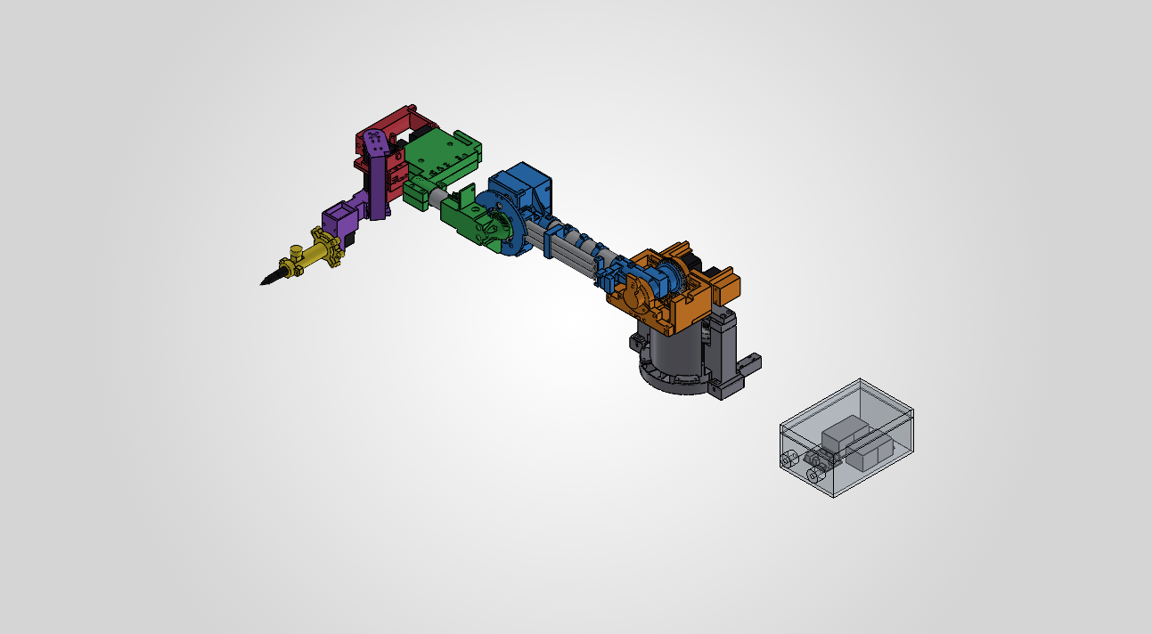
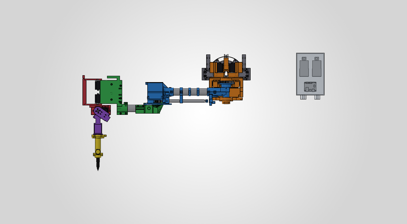
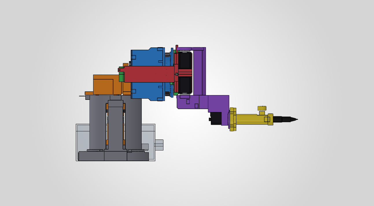
Our final representation in SolidWorks looks like this, with the gray parts being purchased rods and everything else 3D printed links and a manually adjusted end effector for Iteration 1:

Isometric view of the deconstructed robot arm CAD assembly

Top view of the deconstructed robot arm CAD assembly

Side view of the wrist and pen end effector

We have started printing the first plate tonight, and it would likely need around 40 hours of printing, approximately ~900g of filament, which is very close to the 1kg we purchased, so we may need to account for a few more rolls.

Overall the CAD design and simulation work is essentially complete and on schedule, but the biggest risk is with printing and iterating on the prints, as well as ordering the additional parts needed for assembly.

For next week, I plan to:

  1. Print and measure the base and print the base plates first before printing any fully sized arm parts
  2. Outline the remaining order form for additional tubes, screws, filament, and bearings we may need to purchase
  3. Begin printing the finalized build plates in order from bottom to top (with exception of the end effector which we should test early)
  4. Start assembling the printed components and iterate on redesigns quickly

Aaron’s Status Report for 9/26

For the week of September 20th-26th, I continued our Iteration 1 CAD design of our 6DoF robotic arm in SolidWorks. After some discussion with the team, we decided to base our structural requirements on an already established and tested design instead of choosing every dimension from scratch.

We selected the Universal Robots UR3e (which is widely used in different industries), since it was essentially the lightest and smallest model from their catalog. It fulfilled all our design specifications as it contained 6 joints and thus 6 axes of rotation and some safety functions we could take inspiration from.

I used it as our reference and imported its STEP model into SolidWorks, which I used to note down its link lengths, joint placement, proportions, reachable workspace, and then used those measurements as a starting point for our arm. The design will not be an exact copy of the UR3e because it needs to fit to our selected actuators, 3D-printed parts, PSU, and end effector (pen gripper)– however, the reference model would give us a more dependable baseline since they’re already validated dimensions.

This week, I recorded some of the UR3e geometry, specifically its physical limits in CAD and how many degrees of freedom it had for six joints. For our robot, the joint limits need to not collide with themselves or block anything and still let the end effector to reach the object inside of our 0.4m x 0.4m x 0.4m workspace. This work is still in progress since the limits depend on the dimensions of our selected servos and the mechanical design of the 3D printed links.

My Iteration 1 CAD along with the joint simulations and surface modeling (which I’ve modeled as a simple cylindrical surface already), and physics work is scheduled through October 3rd, so I’m currently in progress and on track. What’s still remaining is finalizing joint limits by also finalizing what hardware we’re purchasing, build out the Iteration 1 CAD and run it in the workspace with torque simulations/calculations.

For next week, I plan to:

1. Finalize our hardware parts with their physical limits and calculate the range of motion for all six joints
2. Run a SolidWorks Motion simulation to record the arm’s reachable workspace, I need to figure out how to exactly simulate the physics to see if the weight of the arm is also low enough to sustain the end effector without falling over
3. Determine whether our arm’s shoulder needs a stronger actuator, or some sort of counterbalance (I was thinking of accommodating the design for a vise to hold it down)
4. Update the Iteration 1 SolidWorks assembly based on the simulation results and prepare the CAD files for printing

Aaron’s Status Report for 9/19

For the week of September 13th-19th, I downloaded SolidWorks from the CMU student catalog, and completed the iteration 1 design of our robotic arm in the SolidWorks Design suite. I broke down frequently used 3D CAD models for other 6-axis 3D printed mechanical arms. The current iteration includes the joints, with some prematurely configured motors and power supply and screw holes.

1. Power supply box with its two lids removed

I designed the main arm’s links, with the base and power supply enclosure. I anticipate the current design for the arm itself to be insufficient for the weight of the motors, so I’ll spend the next week calculating the weight of all components and how much torque they will exert on each joint. The links (the printed section between joints) should be sufficient in size and weight to hold the weight of the arm. I also made sure the measurements for the locations of all 24 cover screws were not blocked, and there was enough spacing between printed components without overlaps.

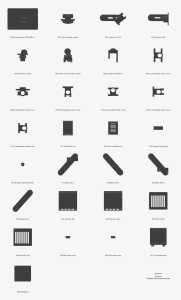
2. 3D printed components
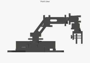
3. Front CAD view of the robot arm
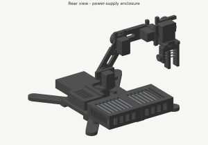
4. Rear CAD view showing the PSU box

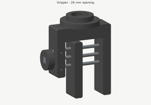
I experimented with pen sleeve designs and ultimately decided on a clawed gripper so the 6th degree of freedom would not limit the pen’s distance from the paper. The gripper now uses one fixed jaw, a sliding jaw, and two 4mm guide rods with an M4 screw that allows the user to manually secure the pen in place. However, this doesn’t allow the robot arm to pick up markers by itself, so we’ll need to tweak this next week.

5. Pen gripper

My iteration 1 CAD and joint, enclosure, and gripper designs, are all scheduled through October 3rd, so it is still in progress and on schedule. I’ve only finished some of the first design and initial load analysis.

For next week, I plan to:

  1. Experiment and design a counterbalance or something stronger to support the shoulder actuator
  2. Define joint limits and degrees of freedom for the six axes
  3. Plan the arm’s path within a fixed workspace that we defined as 0.4m x 0.4m x 0.4m
  4. Verify and further refine the dimensions of the servos, microcontroller, and power supply, among other parts, from the parts list we defined this week
  5. Update the SolidWorks printable files assembly