
For the week of Sep 27th – Oct 3rd, I focused on remodeling our robot to the dimensions of the UR3e robot from last week’s decision. Jonathan and I looked at the UR3e resources online and discovered a spreadsheet containing the transformation matrices for the robot’s positioning and movement of each joint. We wanted to take the dimensions from something that has proved to work and apply our own torque calculations adjusted to our motors and 3d printed links and joint housing.
First, I checked the specifications of our purchased components for the Hiwonder and Feetech smart servos to see if they had compatible communication protocols, which would allow one controller to operate all twelve servos on the same bus.

Above is the UR3e parameters and coordinate transformations that we adopted; the spreadsheet contained variable inputs and visualizations of joint positions on the right, so we could experiment with different positionings. Universal Robotics’ website also contained the downloadable CAD models.

In SolidWorks, I was able to adapt the model’s end effector to hold a pen, then deconstruct the outer casing (since they would require too much filament to print) to preserve the UR3e’s dimensions 1:1.
I then checked whether the servos we got could actually drive the arm with 1:1 dimensions, where I discovered that the shoulder and elbow are close to the servos’ practical limits. To prevent those joints from overheating, I designed for two servos at both the shoulder and elbow, which creates a 3:1 reduction in force and a counterbalance spring based on several joint designs online. My hypothesis is that this reduces unnecessary side loads on the servo shafts and should keep the arm stable since we don’t want it to wobble too much.
I built the updated assembly in SolidWorks with some AI assistance using a scripted workflow; our model now contains 46 printable parts as well as AI-assisted CAD reconstructions of our purchased servos and PSU, as well as some shafts, screws, and tubes that we will likely need to purchase as well to replace sections in which 3D printed parts would bear too much load.
For testing, I tested the assembly by:
- I performed von Mises stress testing through finite-element analysis (FEA) and redesigned weak parts with thicker transitions and rounded bottoms (fillet bottoms) which I’ve seen in the past help with structural integrity
- I used MuJoCo simulations to assemble and visualize the finalized robot, check its motion, and compare the simulated geometry with the SolidWorks assembly
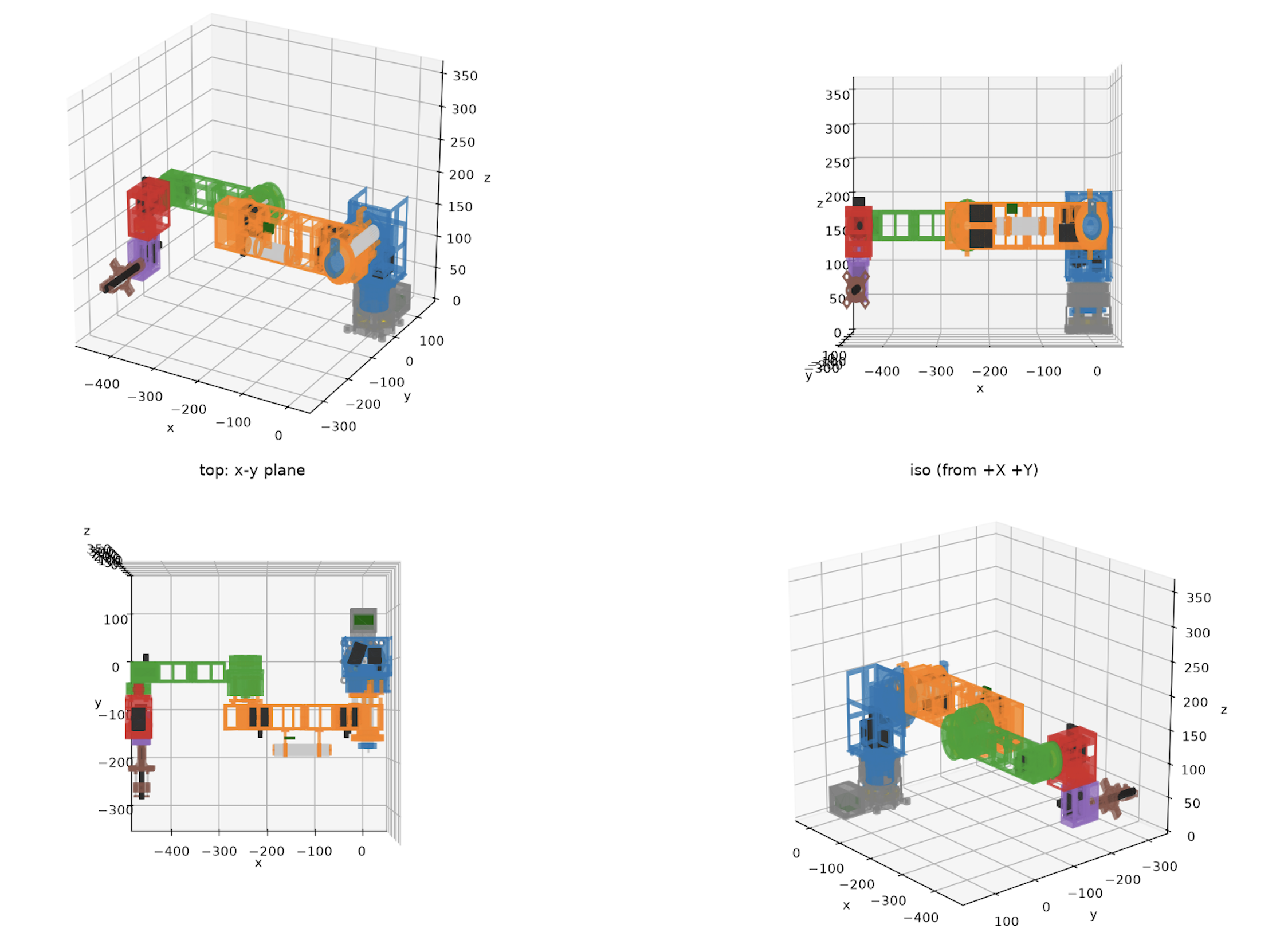
Our final representation in SolidWorks looks like this, with the gray parts being purchased rods and everything else 3D printed links and a manually adjusted end effector for Iteration 1:
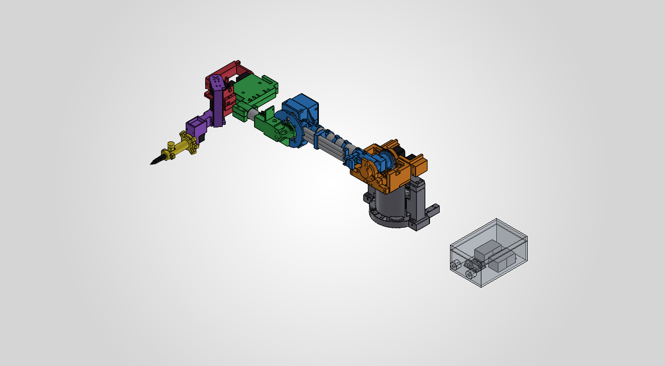
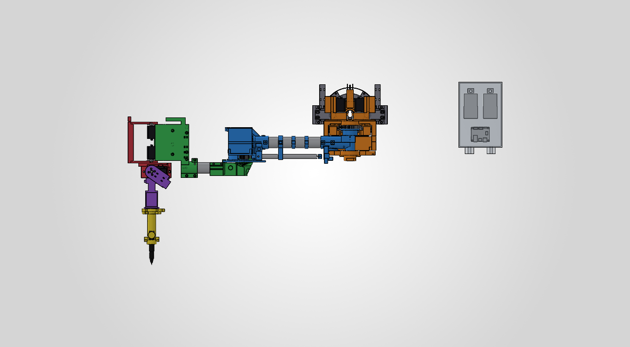
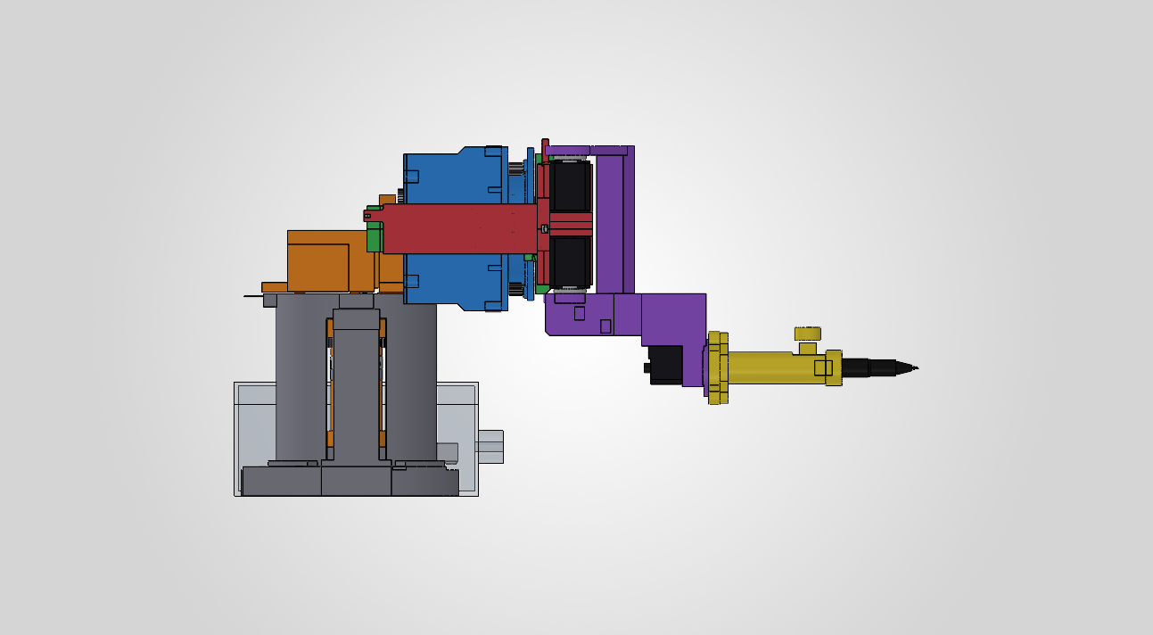
We have started printing the first plate tonight, and it would likely need around 40 hours of printing, approximately ~900g of filament, which is very close to the 1kg we purchased, so we may need to account for a few more rolls.
Overall the CAD design and simulation work is essentially complete and on schedule, but the biggest risk is with printing and iterating on the prints, as well as ordering the additional parts needed for assembly.
For next week, I plan to:
- Print and measure the base and print the base plates first before printing any fully sized arm parts
- Outline the remaining order form for additional tubes, screws, filament, and bearings we may need to purchase
- Begin printing the finalized build plates in order from bottom to top (with exception of the end effector which we should test early)
- Start assembling the printed components and iterate on redesigns quickly