Team Status Report for 9/26/26

Team Status Report

For the week of September 20th–26th, we worked on bringing up the embedded software platform, grounding the mechanical design in a reputable six-axis reference model, refining the Iteration 1 parts list, and preparing the CAD and presentation materials needed for the next stage of the project.

Project Risks & Management Strategies

The biggest risk was figuring out the structural requirements of our manually inferred dimensions on our previous CAD model, as we didn’t have a good basis to figure out if the links would sustain the weight of the joints.

We are managing this risk by comparing our measurements now against Universal Robots’ UR3e, and we aim to calculate the joint torques using the selected components’ estimated masses, and prepare some comprehensive SolidWorks motion and load simulations before printing the final links for this iteration.

Another risk we’ve identified is the integration between the CAD model, ROS2 coordinates, computer vision, and the physical arm. We are attempting to reduce that risk through developing the Jetson software environment early; this week, we’ve already set it up and ran it, and we’re collaborating on defining the CAD workspace and joint constraints before we print the pieces.

System Design Changes

We chose to use the UR3e as reference for dimensions and kinematics, instead of deriving all link lengths and joint placements from scratch which would require continuous testing, and this mechanical specs can get a bit complicated when isn’t the primary expertise or focus of our group. We imported the UR3e STEP model into SolidWorks and recorded its links, joint placement, proportions, and reachable workspace.

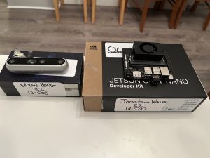
We also set up and installed the OS on our NVIDIA Jetson Orin Nano with JetPack 7 Ubuntu and ROS2. This would give us a physical development platform for testing ROS2 nodes and preparing the coordinate-frame and motion-planning architecture before we assemble the complete arm, so we could allow time extra time for adapting the reference links and joints and configuring the Jetson.

Project Schedule Status

The project remains mostly on schedule. The Jetson environment, initial ROS2 publisher/subscriber test, UR3e reference-model import, early test printing, and preliminary CAD work were completed this week. The Iteration 1 CAD, joint-limit definition, surface modeling, and torque/workspace analysis are scheduled through October 3rd and remain in progress. The parts list and the remaining calculations need to be finalized promptly so that the team can place the hardware order and begin manufacturing without consuming the integration buffer later in the semester.

Team Progress & Highlights

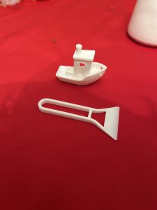
The team successfully configured the Jetson Orin Nano from scratch, installed JetPack 7 Ubuntu and ROS2, and verified the environment with ROS2 publisher and subscriber nodes running simultaneously. We also established an initial 3D-printing environment and completed some basic test prints to estimate manufacturing time and evaluate print settings.
Week-Specific Considerations

Part A: Public Health, Safety, and Welfare
Written by Bryan Hong

When it comes to public health, safety, and welfare, our project may not appear at first glance to directly impact any of the three. However, by placing the means of production into the hands of the artist, we have helped the latter avoid employing the services of a third-party manufacturing company that may rely on unethical labor practices and/or unsafe working conditions. By enabling artists and creators to reproduce their work in-house, our system reduces the reliance on these morally-questionable third party manufacturers, and thus indirectly improves global health, safety, and welfare, ensuring that the physical manifestation of art does not come at the cost of others’ health.

Part B: Social Factors
Written by Aaron Tang

Our robot arm is intended to be used primarily by digital artists, students, and researchers who want to transform a digital line drawing into a physical drawing on curved surfaces.

In order to make this design accessible for social and educational settings, our 1. web interface shouldn’t require experience with robotics, CAD, or any sort of electrical/software engineering. Users should be able to submit a drawing on our interface, select a marker color, and follow the robot’s status and receive clear feedback.

This would make the system valuable for classroom demonstrations and creative environments where artists who don’t have engineering backgrounds can safely and easily reproduce their art. It would also take into consideration people who have difficulty drawing manually on large, elevated, or unusually positioned surfaces.

We have also considered some concerns that robotic drawing tools could replace human creativity. Our goal is to create a tool to assist artists, not replace them: the user should ultimately still be responsible for their own artwork and creative decisions, while the robot simply transfers that work exactly stroke by stroke to a physical surface. The system should also respect ownership and consent by reproducing only artwork that artists consent to, and keeping submitted drawings under the user’s control.

Part C: Economic Factors
Written by Jonathan Waller

Our 6DOF drawing robot addresses economic factors in production and consumption by providing a low-cost, accessible alternative to expensive industrial machinery. By utilizing standard off-the-shelf smart servos, 3D-printed structural components, and open-source software, our design significantly reduces the bill of materials. This allows the 6DOF arm to be affordable relative to its capabilities. The system was designed with independent creators and digital artists in mind, allowing them to produce small batches of custom physical works directly from their digital art. Instead of relying on costly third-party manufacturing services or full-scale assembly lines, artists can preserve their preferred digital workflow, fine-tune their designs locally, and economically handle low-volume production without a heavy financial investment.
Bryan’s Status Report for 9/26/2026

For the week of September 20th – 26th,  I focused on continuing my research and development into Iteration 1 of our 6-DOF robot arm. After initially choosing a YOLO model for AprilTag (used for calibration) detection, my team and I discussed using the NVIDIA Isaac ROS or OpenCV instead, since it is more optimized for AprilTag detection. However, since our design has not yet been fully finalized, much of our final electrical components have not been finalized yet as we do not have accurate enough data for torque calculations. In addition, we are still investigating whether a dedicated microcontroller will be necessary for our final system.

One of my main areas of research this week was determining how AprilTag tracking could be incorporated into our system. I investigated using OpenCV-based and Isaac ROS AprilTag detection approaches as alternatives to using a YOLO-based object-detection pipeline. OpenCV would potentially provide a simpler solution for identifying AprilTags, since the architecture is quite easy to use, which cannot be as easily said about Isaac ROS. This could simplify the computer-vision pipeline compared to training a YOLO model specifically for AprilTag detection. However, I am still evaluating the tradeoffs between the approaches, specifically in terms of detection accuracy, implementation ability, and how well each method would integrate with the NVIDIA Jetson Orin Nano and Intel RealSense Depth Camera D455.

I also continued investigating the smart bus serial servo motors that we discussed last week. While Hiwonder, Feetech, and Waveshare are still candidates, I was unable to definitively select the motors because our team has not yet finalized the Iteration 1 design, and as a result, we do not have an accurate estimation for the required torque at each joint. Therefore, we decided to hold off for the time being to confirm our final Iteration 1 design, since prematurely ordering motors that are too weak to support the joints is a real concern. In the meantime, I will continue searching more approved vendors such as DigiKey to source smart bus serial motors from.

Overall, this week was primarily focused on narrowing down the computer-vision and embedded-system architecture while continuing to work with my team on the overall design. Since our Iteration 1 design is still a work in progress, my work has consisted more heavily of research and comparison instead of final component selection. Once the mechanical design is finalized, I will be able to use the resulting simulation data to make appropriate decisions about the servo motors, power requirements, and camera placement.

For next week, I aim to complete the following:

  • Continue comparing OpenCV AprilTag detection against YOLO-based detection and determine which approach is better suited for our system
  • Test or prototype AprilTag tracking using the NVIDIA Jetson and camera setup.
  • Collaborate with the team to finalize the Iteration 1 mechanical and electrical design.
  • Use updated simulation data to determine the torque requirements for each smart bus serial servo.
  • Narrow down and finalize the specific smart bus serial servo motors for each joint.
  • Assist the team with refining the master parts list, including component prices, links, specifications, and quantities.

Jonathan’s Status Report for 9/26/26

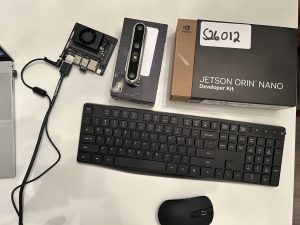
For this second week, I dedicated my time toward bringing up our robot’s software and hardware stacks, establishing our 3D printing workflow, assisting with mechanical calculations, and preparing for our upcoming design presentation. A major milestone for this week was receiving our embedded computing platform and setting up a functional, local ROS2 development environment directly on the physical hardware (see below).

I spent significant time getting the NVIDIA Jetson Orin Nano up and running from scratch. Because the board arrived without an operating system or peripherals, I sourced a DisplayPort cable and a high-speed microSD card for storage, then flashed the Jetson with JetPack 7 Ubuntu. Once the OS was configured, I installed essential command-line tools like tmux and vim alongside ROS2, verifying system stability and environment setups by running the first ROS2 test with 2 publisher and subscriber nodes running simultaneously on the device. Additionally, I helped establish our team’s 3D printing workflow by slicing and executing test prints to evaluate how much time each print will take (photos of these test prints will be on this week’s team report).

Beyond individual setup tasks, I collaborated with the team on refining our master hardware parts list so we can finalize and submit our order for Iteration 1. I also worked alongside the team on CAD Iteration 1, initiating torque and workspace calculations to inform joint placements, limb lengths, and motor specs. Finally, I drafted content for our upcoming design presentation and spent time practicing, as I will be serving as the team’s primary presenter.

I am mostly on track relative to our project roadmap, though we need to make sure the parts list is finalized soon and finish our calculations on torque and workspace in the next few days.

For next week, I plan to:

  • Finalize and submit our master hardware parts list for Iteration 1 components.
  • Deliver our team’s design presentation and analyze the feedback from faculty and TAs.
  • Begin setting up the general software project layout (ROS2) and outline the initial tf2 frame tree structure.
  • Finish torque and workspace calculations with the team to finalize motor placements and limb dimensions in CAD.

Aaron’s Status Report for 9/26

For the week of September 20th-26th, I continued our Iteration 1 CAD design of our 6DoF robotic arm in SolidWorks. After some discussion with the team, we decided to base our structural requirements on an already established and tested design instead of choosing every dimension from scratch.

We selected the Universal Robots UR3e (which is widely used in different industries), since it was essentially the lightest and smallest model from their catalog. It fulfilled all our design specifications as it contained 6 joints and thus 6 axes of rotation and some safety functions we could take inspiration from.

I used it as our reference and imported its STEP model into SolidWorks, which I used to note down its link lengths, joint placement, proportions, reachable workspace, and then used those measurements as a starting point for our arm. The design will not be an exact copy of the UR3e because it needs to fit to our selected actuators, 3D-printed parts, PSU, and end effector (pen gripper)– however, the reference model would give us a more dependable baseline since they’re already validated dimensions.

This week, I recorded some of the UR3e geometry, specifically its physical limits in CAD and how many degrees of freedom it had for six joints. For our robot, the joint limits need to not collide with themselves or block anything and still let the end effector to reach the object inside of our 0.4m x 0.4m x 0.4m workspace. This work is still in progress since the limits depend on the dimensions of our selected servos and the mechanical design of the 3D printed links.

My Iteration 1 CAD along with the joint simulations and surface modeling (which I’ve modeled as a simple cylindrical surface already), and physics work is scheduled through October 3rd, so I’m currently in progress and on track. What’s still remaining is finalizing joint limits by also finalizing what hardware we’re purchasing, build out the Iteration 1 CAD and run it in the workspace with torque simulations/calculations.

For next week, I plan to:

1. Finalize our hardware parts with their physical limits and calculate the range of motion for all six joints
2. Run a SolidWorks Motion simulation to record the arm’s reachable workspace, I need to figure out how to exactly simulate the physics to see if the weight of the arm is also low enough to sustain the end effector without falling over
3. Determine whether our arm’s shoulder needs a stronger actuator, or some sort of counterbalance (I was thinking of accommodating the design for a vise to hold it down)
4. Update the Iteration 1 SolidWorks assembly based on the simulation results and prepare the CAD files for printing

Bryan’s Status Report for 9/19/26

For the week of September 13th – 19th, I primarily focused on researching electrical and embedded-system components required for Iteration 1 of our 6-DOF surface-drawing robot arm. My work centered on identifying suitable power supplies, smart serial bus servo motors, microcontrollers, and supporting drivers. In addition, I investigated object-detection models that could run on the NVIDIA Jetson platform, specifically the YOLOv26 model and the process of training and deploying the model using Google Colab.

In order to provide adequate power to the NVIDIA Jetson Orin Nano, Intel RealSense Depth Camera D455, 6 smart serial bus servo motors, and possibly a microcontroller, I found that a MeanWell LRS-350-24 24V, 14.6A, 350.4W power supply would be the safest bet, paired with a fuse distributor; it would be easier to have a pair of wires from the power supply to the fuse distributor than to have multiple wires coming straight from the power supply. Given  that 24V may be too much for certain components (namely the Jetson), I figured that we would also require a 24V to 12V step-down converter to avoid overcurrent.

The biggest change from our original concept to the Iteration 1 design was the transition to using smart bus serial servo motors rather than traditional stepper motors. This is because these smart servos provide live position data, which we would have otherwise needed to reverse-engineer using traditional servos. For a project like this that requires exact precision, smart servos would save our group much-needed R&D time that could be used for testing and verification. As we do not yet have accurate simulation data from AutoCAD, we can only estimate our torque requirements. From my preliminary research, I found that Hiwonder, Feetech, and Waveshare offer affordable servos within our budget; I found Robotis Dynamixel servos cost upwards of $100 each, which is unsustainable.

Our team also explored the prospect of using an object detection model to run on the Jetson, for the purpose of identifying different color pens to pick up. Although this is not yet an official requirement, I conducted research into how to implement this. After comparing current commercial object detection models such as SSD, YOLO, DETR, and Faster R-CNN, I established that the only model to combine high accuracy, real-time detection, and compatibility with the Jetson Orin Nano platform was the YOLO family of models. More specifically, there are a variety of YOLOv26 models that are available based on inference speed and GPU strength. Since we do not require many detection classes, the YOLOv26n (nano) model will be sufficient.

Reinforcement learning for the model will be performed on Google Colab, since high-end GPU accelerators are free. To create the dataset, the workflow that Ultralytics provides will be sufficient, since it allows for drawing specific detection polygons onto input images and the simplified creation of different detection classes. As for implementation on the Jetson, I would use OpenCV to grab frames from the camera feed, run the trained YOLOv26n model (exported to a TensorRT-optimized engine file), then output coordinates for the object detection box.

For next week, I aim to complete the following:

  • set up Ultralytics workspace
  • start training YOLOv26 model on dataset with different color pens
  • collaborate with team to finalize design of Iteration 1 and obtain accurate simulation data for servo torque requirements
  •  assist team to refine master parts list into spreadsheet with prices, links, and any other information
    • specifically finalize brands of smart bus serial servo motors

Team Status Report for 9/19/26

Team Status Report

For this week, our team focused on defining the master project timeline, evaluating key system risks, and refining our initial mechanical and electrical hardware architectures.

Project Risks & Management Strategies

Our team identified three primary technical risks that could jeopardize project success and established corresponding management strategies. First, structural deflection in our 3D-printed links under joint motor loads could degrade drawing accuracy. We are running SolidWorks stress and torque simulations on Iteration 1 link geometries prior to printing, with a contingency plan to insert internal aluminum reinforcement rods or increase print wall thickness if excessive flex occurs. Second, dynamic surface geometries could push the arm past its physical reach or into joint singularities. We defined a strict 0.4m *0.4m * 0.4m target workspace and designed our path planner to bound trajectories, utilizing an adjustable mounting base to reposition targets as needed. Finally, subsystem integration between ROS2, microcontrollers, vision tracking, and physical hardware presents a late-stage bottleneck, so we proactively restructured our timeline to include dedicated integration buffer weeks.

System Design Changes

We updated our system block diagram this week to replace traditional stepper motors with smart serial bus servo motors for primary joint actuation. Smart servos provide built-in position feedback controllers and support daisy-chain communication, which drastically reduces physical wire runs and bulk throughout the 6DOF arm structure. While smart servos carry a slightly higher unit cost than bare steppers, they eliminate the need to purchase separate motor driver breakout boards for each joint and significantly reduce wire harness assembly time, keeping overall project costs and risks on track.

Project Schedule Status

The team completed a comprehensive review and revamp of our master schedule this week. We explicitly incorporated dedicated buffer space for system integration and physical hardware debugging toward the end of the term. With these adjustments in place, our overall project progress remains on schedule relative to our updated roadmap.

Team Progress & Highlights

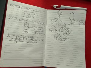
On the design front, the team held a design review forum to critique our preliminary Iteration 1 SolidWorks draft, successfully identifying key structural constraints around shoulder torque distribution, arm reach, and 3D printing clearances. Additionally, we designed a universal object target mounting base equipped with AprilTags. This mounting base allows dynamic target surfaces—such as cups, curved plates, or flat planes—to be secured firmly in the workspace while providing a clear coordinate frame for the vision system to detect relative to the robot base.

Initial team sketches for helping the robot identify the base and object with AprilTags
1. Initial team sketches for helping the robot identify the base and object with AprilTags

  1. Iteration 1 SolidWorks CAD draft overview showing initial joint and enclosure layout
  2. AprilTag object target mounting base design diagram

Jonathan’s Status Report for 9/19/26

For this first week, I dedicated most of my time toward establishing the software foundation and architecture for our 6DOF surface-drawing robot arm. I focused on investigating robotic software stacks to ensure our arm can reliably handle inverse kinematics, dynamic surface mapping, and low-level servo communication.

I spent significant time evaluating the ROS2 ecosystem and selecting key packages for our software pipeline. I investigated MoveIt 2 for 6DOF trajectory planning and inverse kinematics (IK) solving, alongside ros2_control to serve as the hardware abstraction layer between ROS2 nodes and our physical joint controllers. To handle coordinate frame transformations between the robot base, camera optical frame, and variable target surfaces (planes, curves, cylinders, half-pipes), I started planning the use of a frame tree structure using tf2. For perception, I looked into integrating apriltag_ros and OpenCV vision models, as well as evaluating NVIDIA Isaac ROS packages (specifically isaac_ros_apriltag) to leverage GPU-accelerated pose estimation on the Jetson Nano paired with an Intel RealSense depth camera we will be renting from the ECE department. Additionally, I researched using micro-ROS on a microcontroller to handle low-latency serial bus communication if we decide to use things like bare stepper motors. I alsoexplored vis2 and RViz2 setups for kinematic visualization.

For later reference, here are the ROS2 libraries and tools I researched:

  • MoveIt 2
  • ros2_control nodes
  • tf2
  • apriltag_ros and OpenCV (OpenCV would be easier to test and bring up by itself but more difficult to integrate into the final product)
  • NVIDIA Isaac ROS (for CV and more out of the Jetson Nano)
  • micro-ROS
  • vis2 and RViz2

Beyond software, I participated in team trade-off discussions regarding joint selection and workspace reach, helping determine how our software nodes will enforce physical joint limits during surface tracking. I also created our team’s local ROS2 repository, initialized the workspace directory structure, and wrote initial package configuration files to prepare for integration.

I am scheduled on track relative to our project roadmap.

For next week, I plan to:

  1. Finalize the local ROS2 software workspace structure and pull in required drivers and third-party dependencies.
  2. Build out the initial infra for tf2 robot link tree and create a basic URDF/XACRO model representing our Iteration 1 arm parameters.
  3. Assist the team in finalizing the master hardware parts list (servos, bearings, microcontrollers, power supply).
  4. Collaborate with Aaron on verifying CAD Iteration 1 dimensions to ensure motor mounts and sensor placements align with our software node assumptions.

Aaron’s Status Report for 9/19

For the week of September 13th-19th, I downloaded SolidWorks from the CMU student catalog, and completed the iteration 1 design of our robotic arm in the SolidWorks Design suite. I broke down frequently used 3D CAD models for other 6-axis 3D printed mechanical arms. The current iteration includes the joints, with some prematurely configured motors and power supply and screw holes.

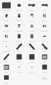
1. Power supply box with its two lids removed

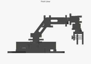
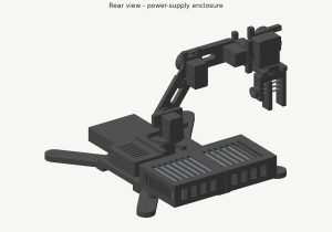
I designed the main arm’s links, with the base and power supply enclosure. I anticipate the current design for the arm itself to be insufficient for the weight of the motors, so I’ll spend the next week calculating the weight of all components and how much torque they will exert on each joint. The links (the printed section between joints) should be sufficient in size and weight to hold the weight of the arm. I also made sure the measurements for the locations of all 24 cover screws were not blocked, and there was enough spacing between printed components without overlaps.

2. 3D printed components
3. Front CAD view of the robot arm
4. Rear CAD view showing the PSU box

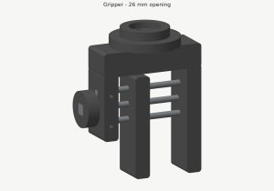
I experimented with pen sleeve designs and ultimately decided on a clawed gripper so the 6th degree of freedom would not limit the pen’s distance from the paper. The gripper now uses one fixed jaw, a sliding jaw, and two 4mm guide rods with an M4 screw that allows the user to manually secure the pen in place. However, this doesn’t allow the robot arm to pick up markers by itself, so we’ll need to tweak this next week.

5. Pen gripper

My iteration 1 CAD and joint, enclosure, and gripper designs, are all scheduled through October 3rd, so it is still in progress and on schedule. I’ve only finished some of the first design and initial load analysis.

For next week, I plan to:

  1. Experiment and design a counterbalance or something stronger to support the shoulder actuator
  2. Define joint limits and degrees of freedom for the six axes
  3. Plan the arm’s path within a fixed workspace that we defined as 0.4m x 0.4m x 0.4m
  4. Verify and further refine the dimensions of the servos, microcontroller, and power supply, among other parts, from the parts list we defined this week
  5. Update the SolidWorks printable files assembly